




































































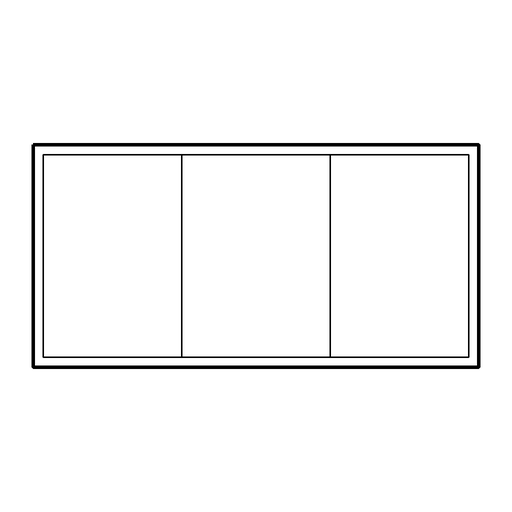
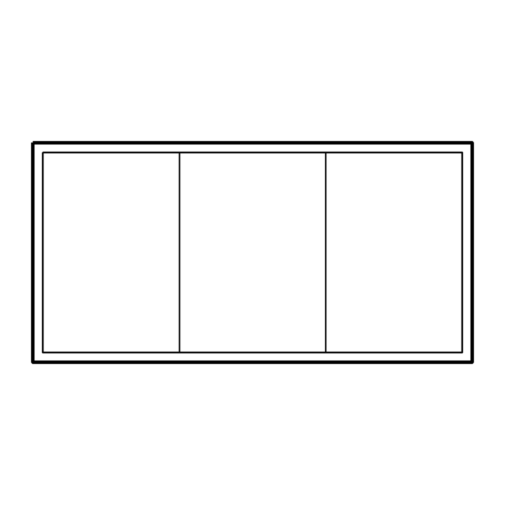


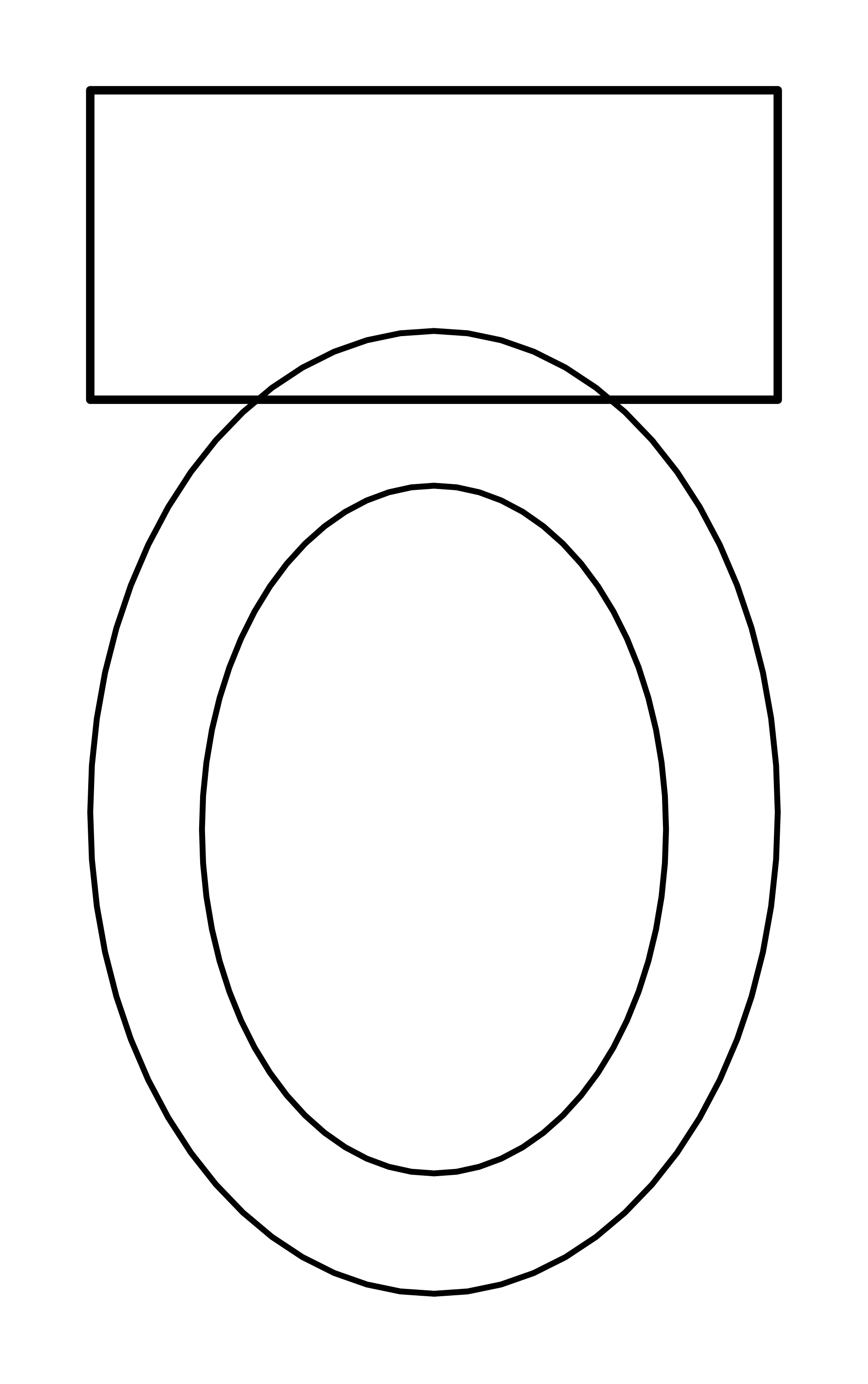
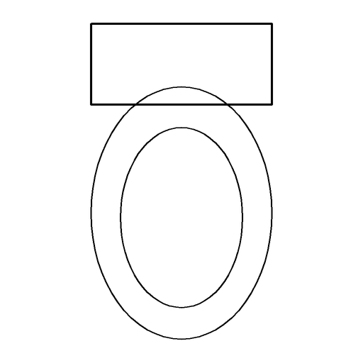





























































































Skiaform

Skiaform / Guides / Drawing tools

Free architectural drawing symbols

Floor plan symbols Free architectural symbols in SVG, PNG and DXF

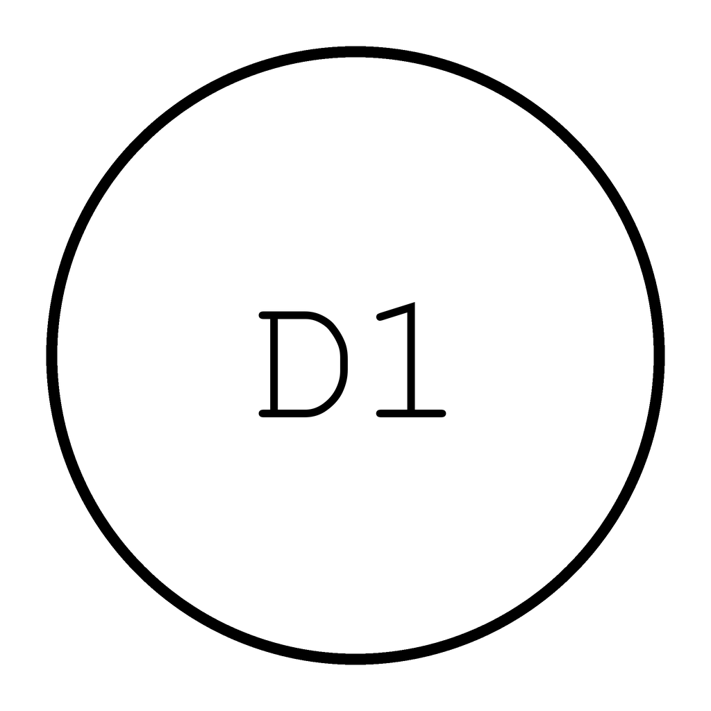
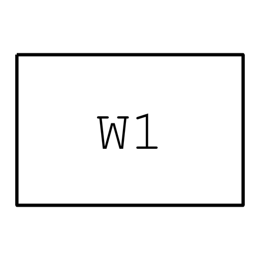
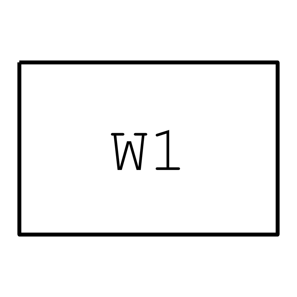
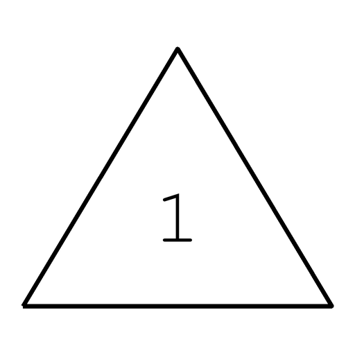
Find doors, windows, stairs, kitchen fixtures, furniture and electrical symbols for your plan. Browse original drawings, check each symbol's typical size, then download a vector, transparent image or CAD block. Take the complete library or print a floor plan symbols PDF as a reference beside your drawing.

Find a symbol for your plan

Choose a group or search by name. Select a drawing to see its size and individual downloads. Physical objects use typical model dimensions; annotation and electrical marks use paper dimensions. Preview drawings are fitted to each cell.

76 symbols / all groups

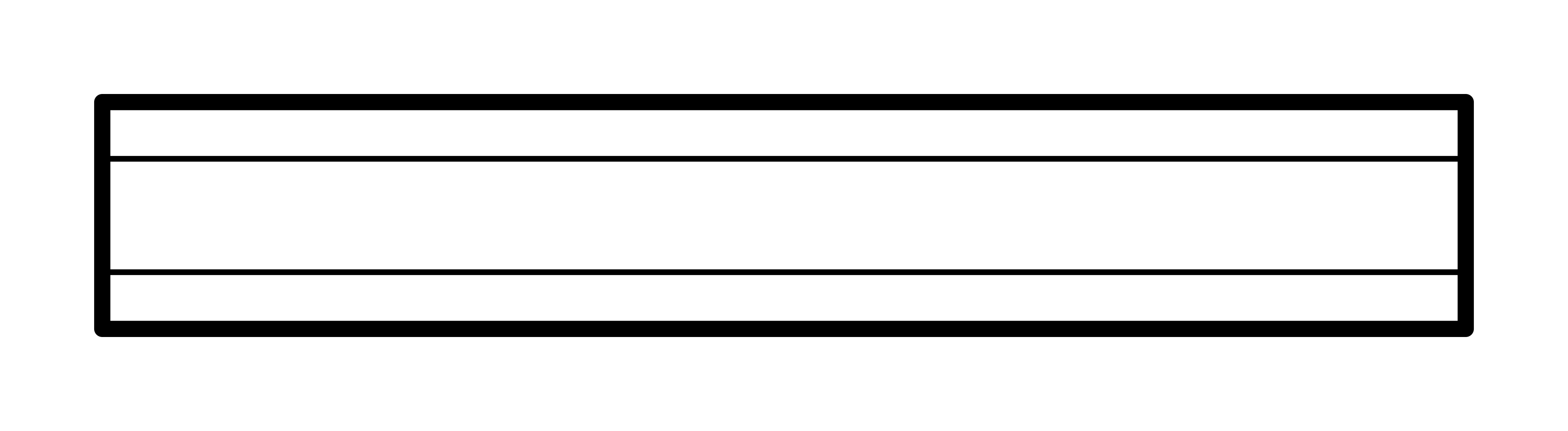
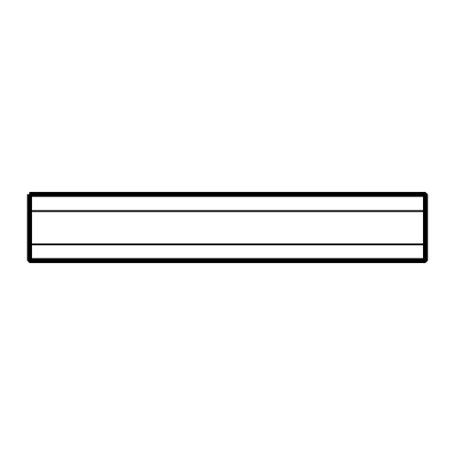
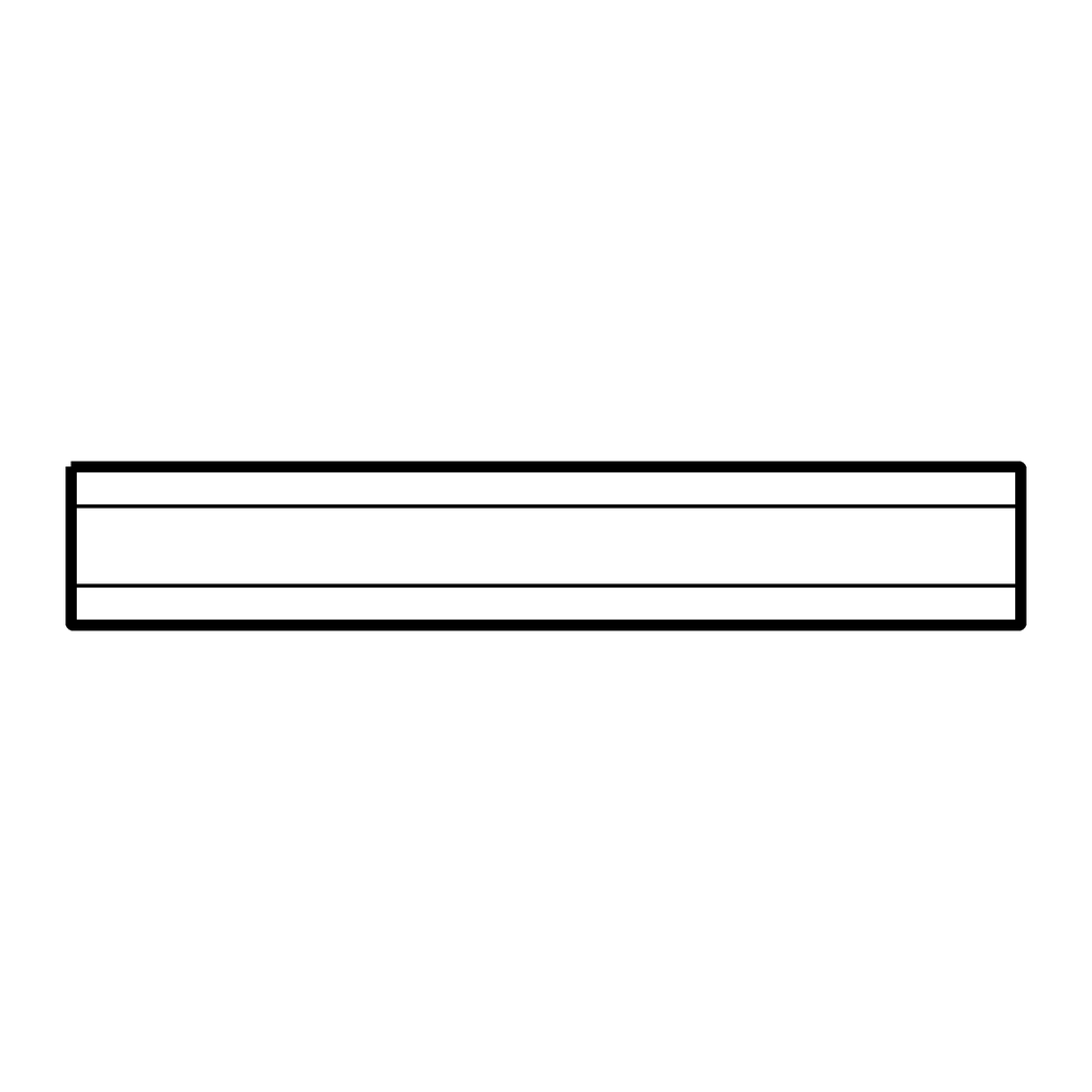
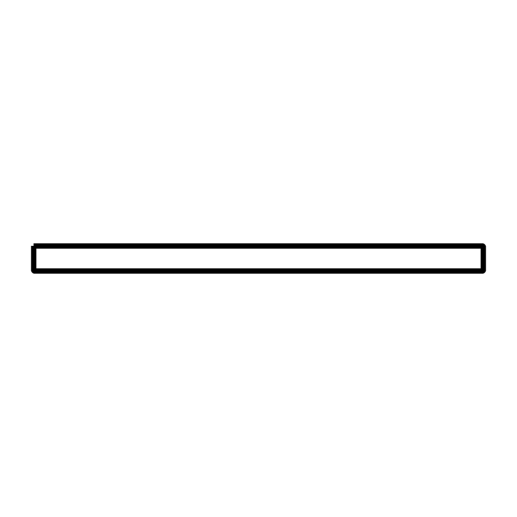
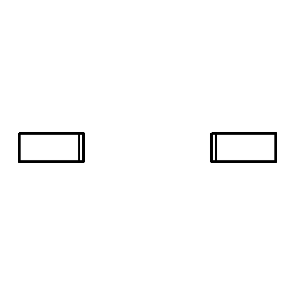
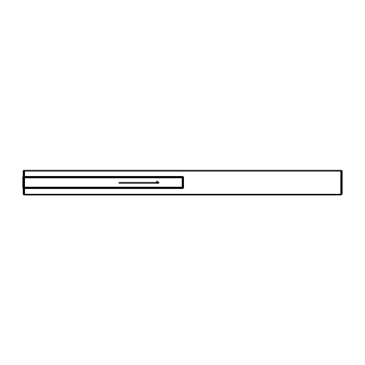
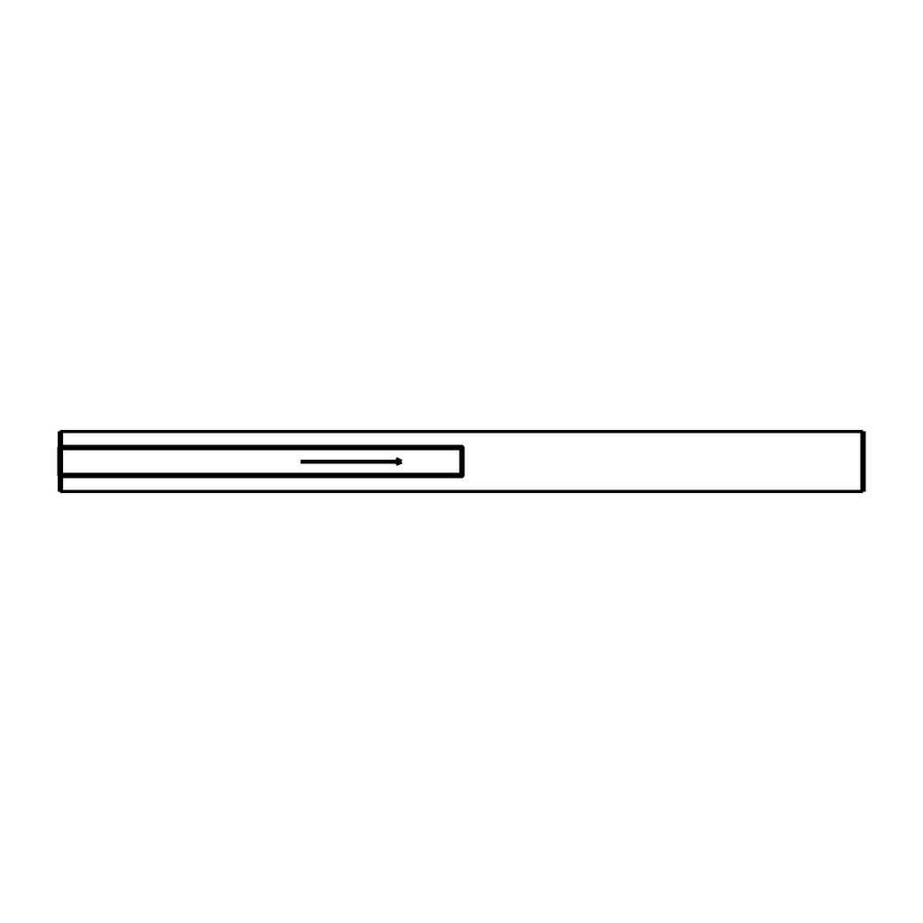
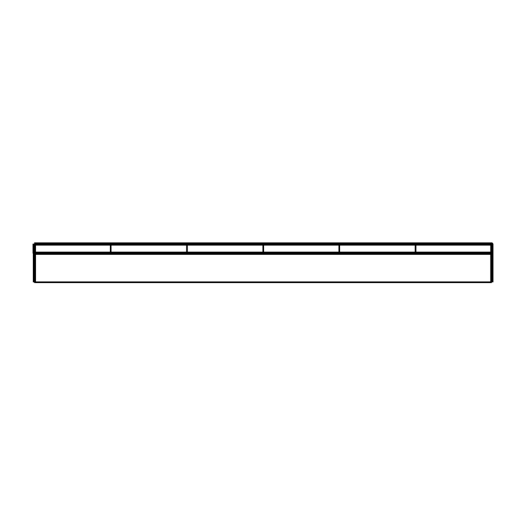
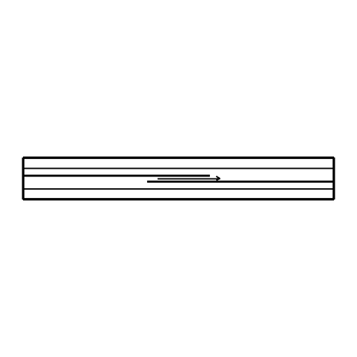
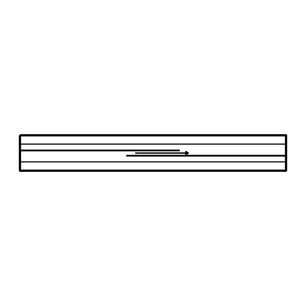
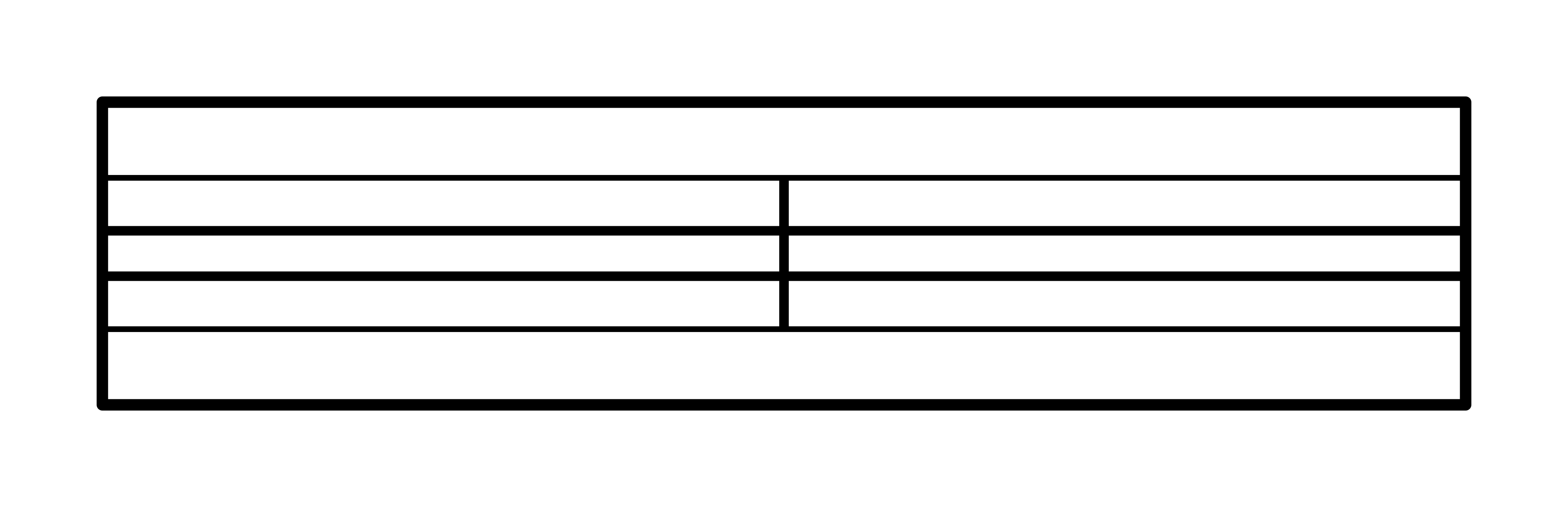
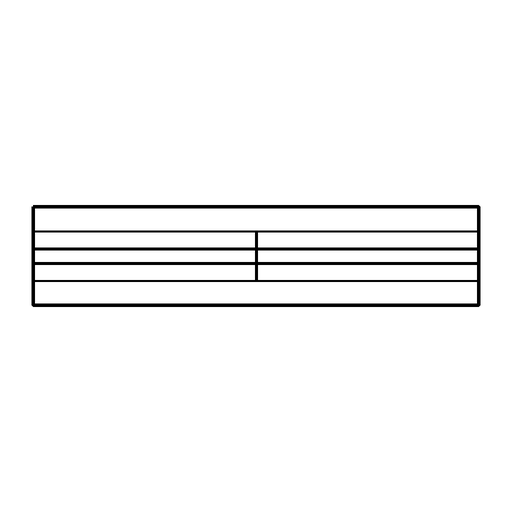
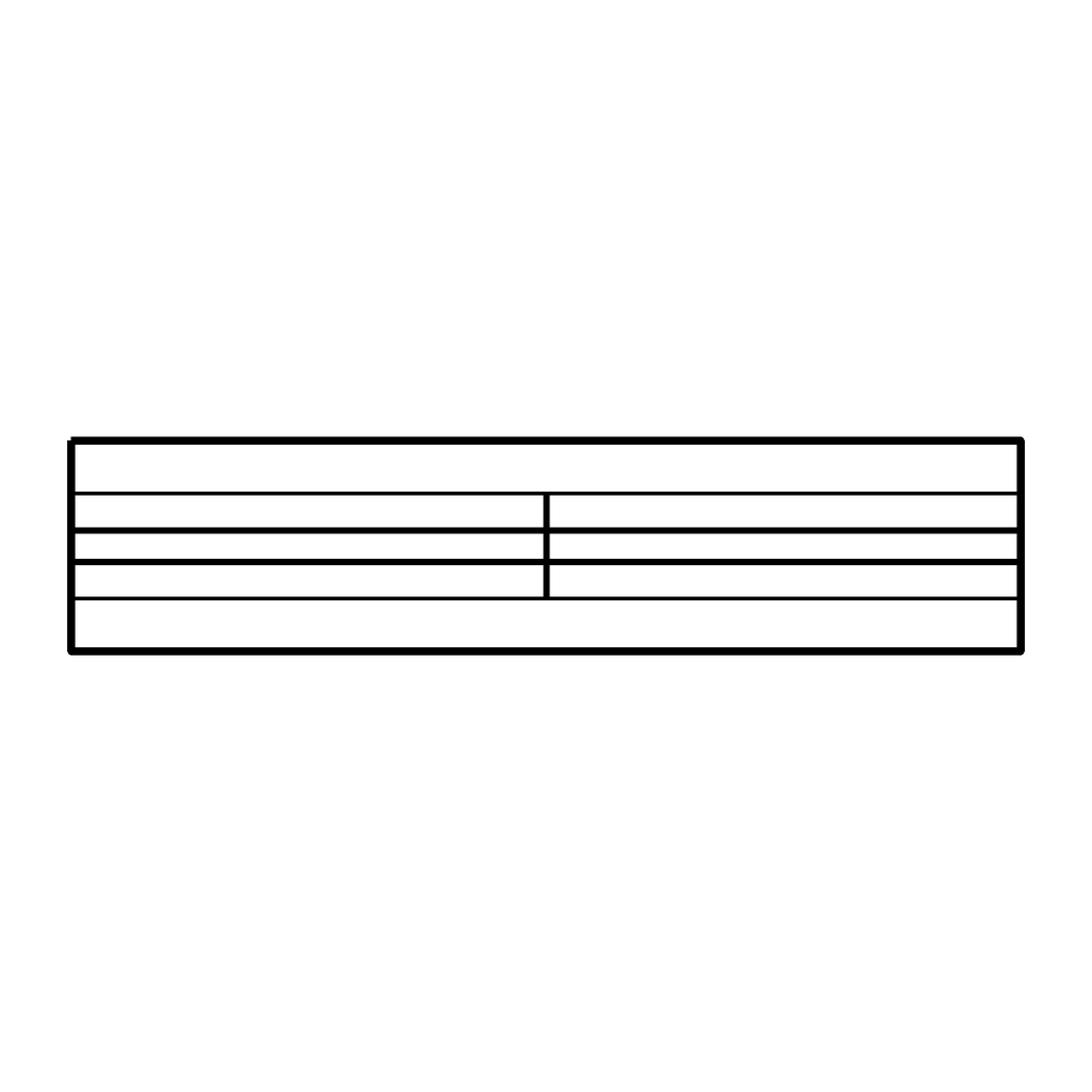
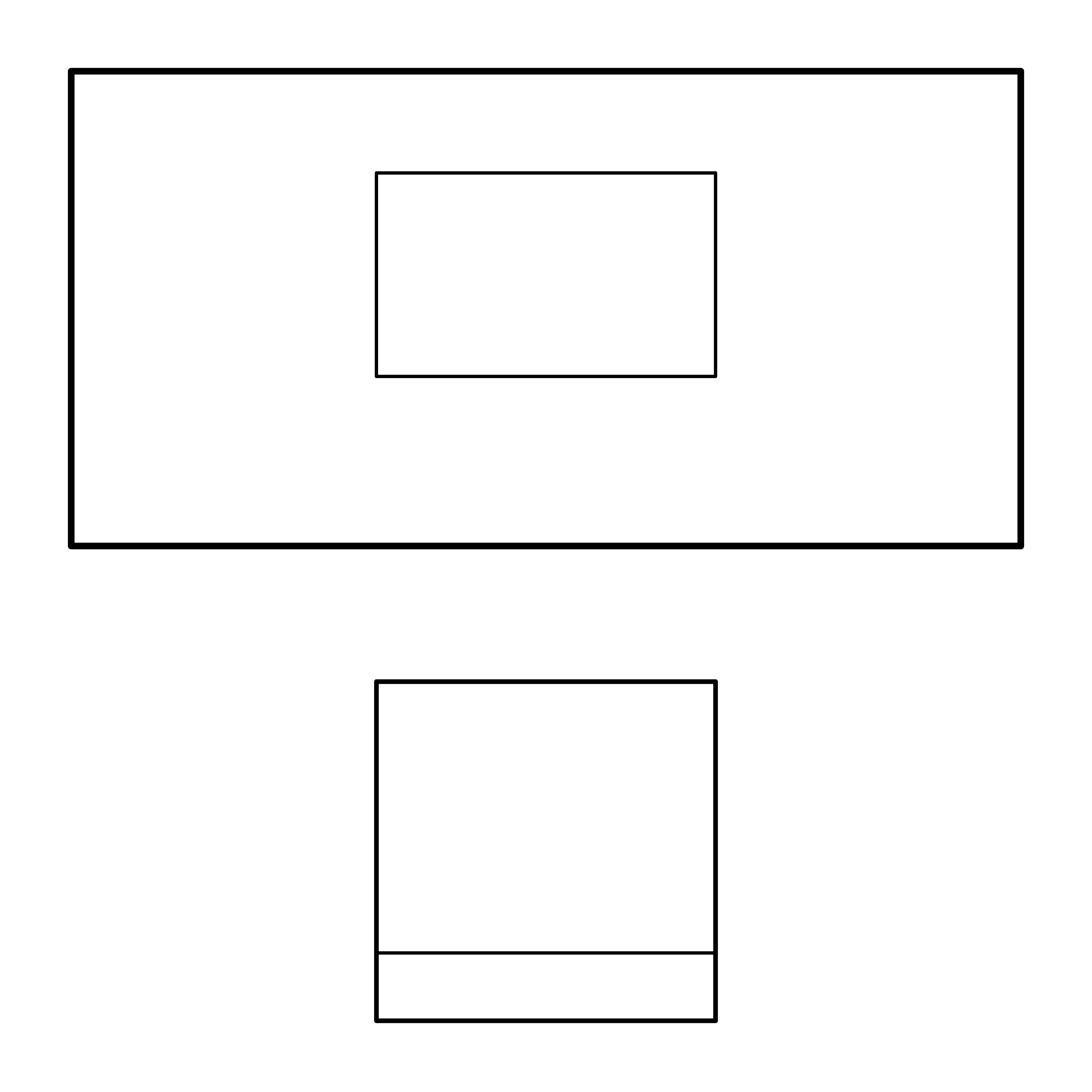
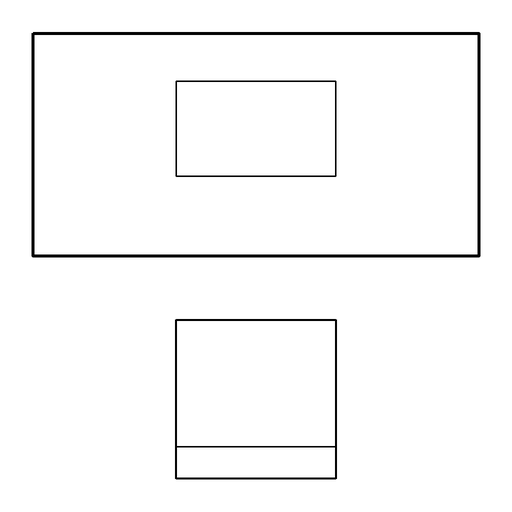
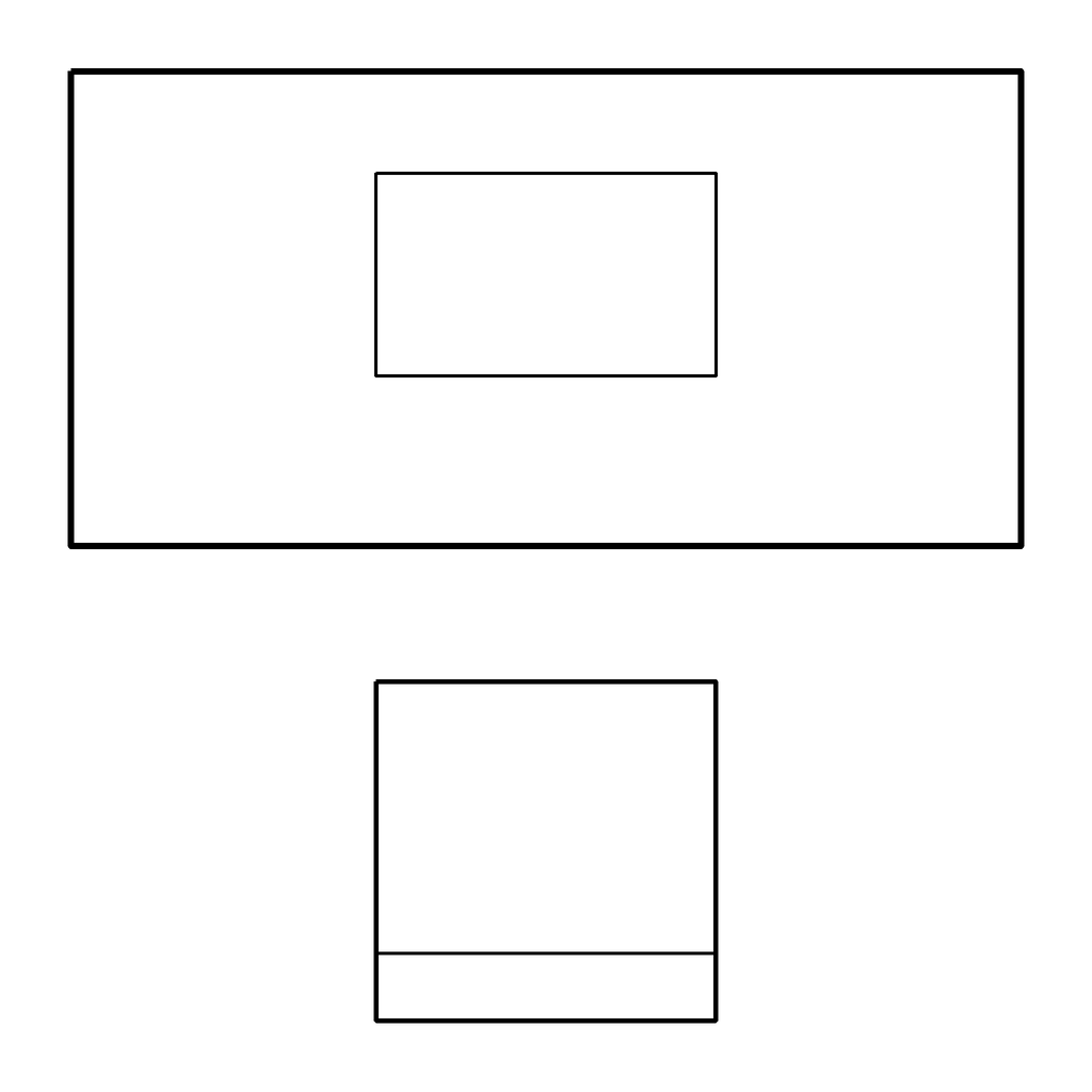
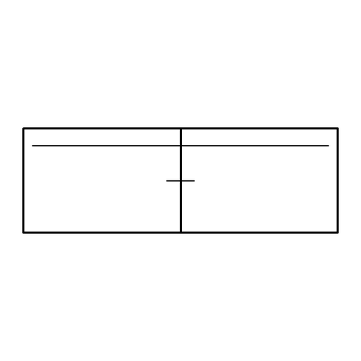
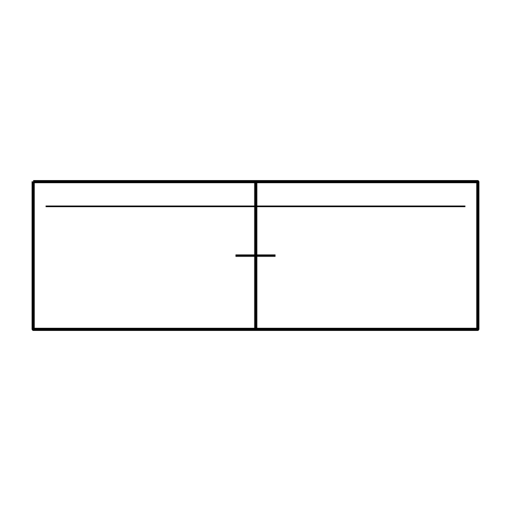
01 / Walls and openingsExterior wallTypical / 1800 × 300 mm

True size model geometry
Typical size: 1800 × 300 mm.
Overall drawn extents: 1800 × 300 mm / 70.866 × 11.811 in.

Typical wall segment; opening symbols show a 900 mm clear gap.

Sizes are not code requirements. DXF layer: A-WALL. Select import units explicitly and use insertion scale 1. SVG includes margin; PNG is fitted to a square transparent canvas.

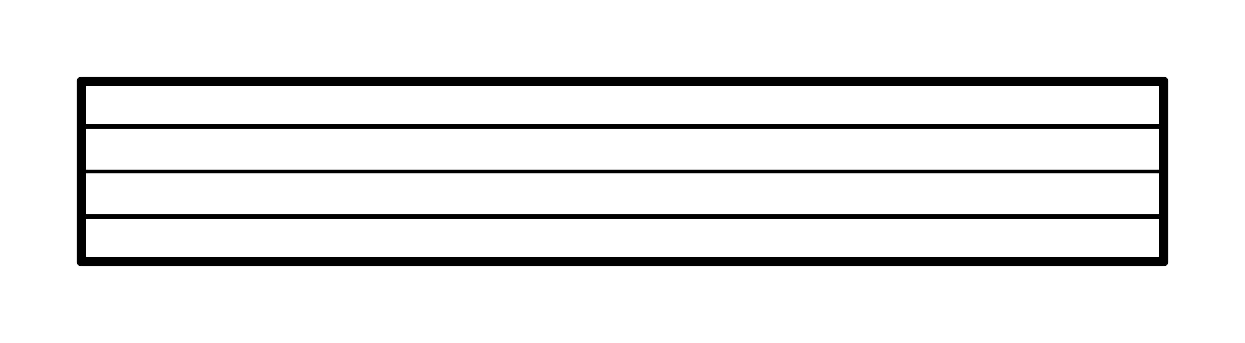
02 / Walls and openingsInterior partitionTypical / 1800 × 100 mm

True size model geometry
Typical size: 1800 × 100 mm.
Overall drawn extents: 1800 × 100 mm / 70.866 × 3.937 in.

Typical wall segment; opening symbols show a 900 mm clear gap.

Sizes are not code requirements. DXF layer: A-WALL. Select import units explicitly and use insertion scale 1. SVG includes margin; PNG is fitted to a square transparent canvas.

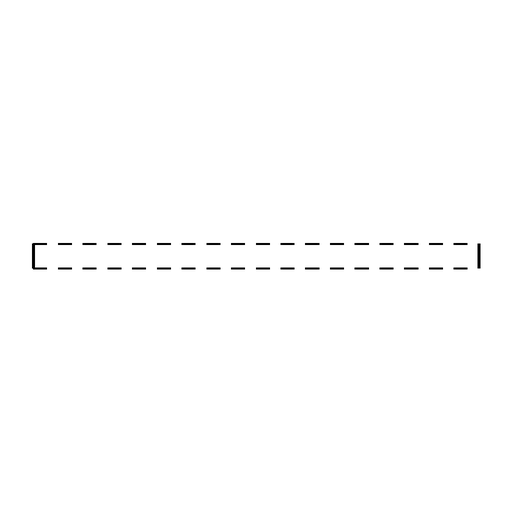
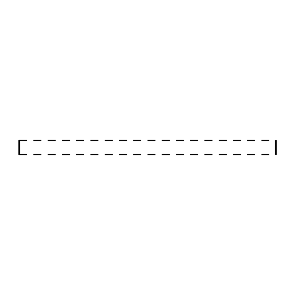
03 / Walls and openingsDemolished wallTypical / 1800 × 100 mm

True size model geometry
Typical size: 1800 × 100 mm.
Overall drawn extents: 1800 × 100 mm / 70.866 × 3.937 in.

Typical wall segment; opening symbols show a 900 mm clear gap.

Sizes are not code requirements. DXF layer: A-WALL. Select import units explicitly and use insertion scale 1. SVG includes margin; PNG is fitted to a square transparent canvas.

04 / Walls and openingsWall openingTypical / 1800 × 200 mm

True size model geometry
Typical size: 1800 × 200 mm.
Overall drawn extents: 1800 × 200 mm / 70.866 × 7.874 in.

Typical wall segment; opening symbols show a 900 mm clear gap.

Sizes are not code requirements. DXF layer: A-WALL. Select import units explicitly and use insertion scale 1. SVG includes margin; PNG is fitted to a square transparent canvas.

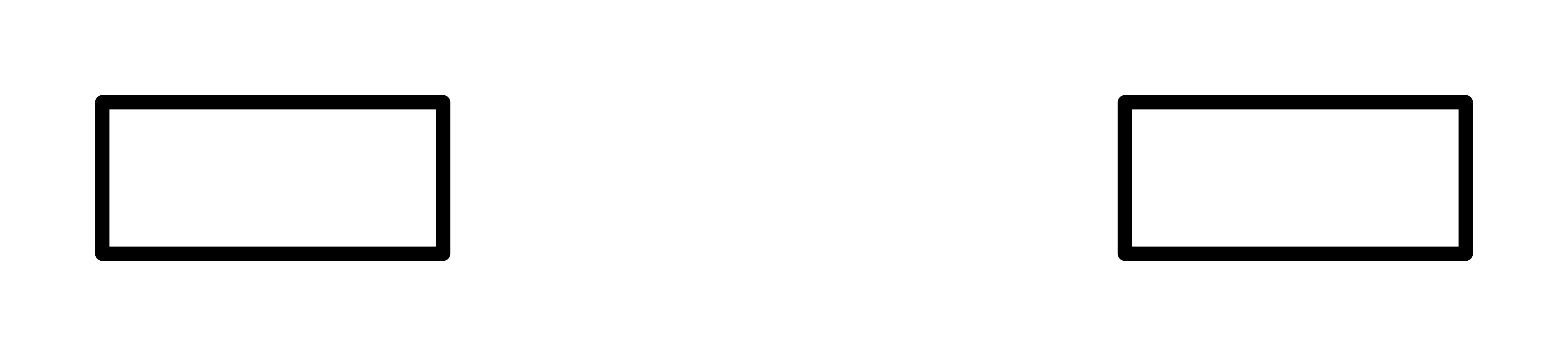
05 / Walls and openingsCased openingTypical / 1800 × 200 mm

True size model geometry
Typical size: 1800 × 200 mm.
Overall drawn extents: 1800 × 200 mm / 70.866 × 7.874 in.

Typical wall segment; opening symbols show a 900 mm clear gap.

Sizes are not code requirements. DXF layer: A-WALL. Select import units explicitly and use insertion scale 1. SVG includes margin; PNG is fitted to a square transparent canvas.

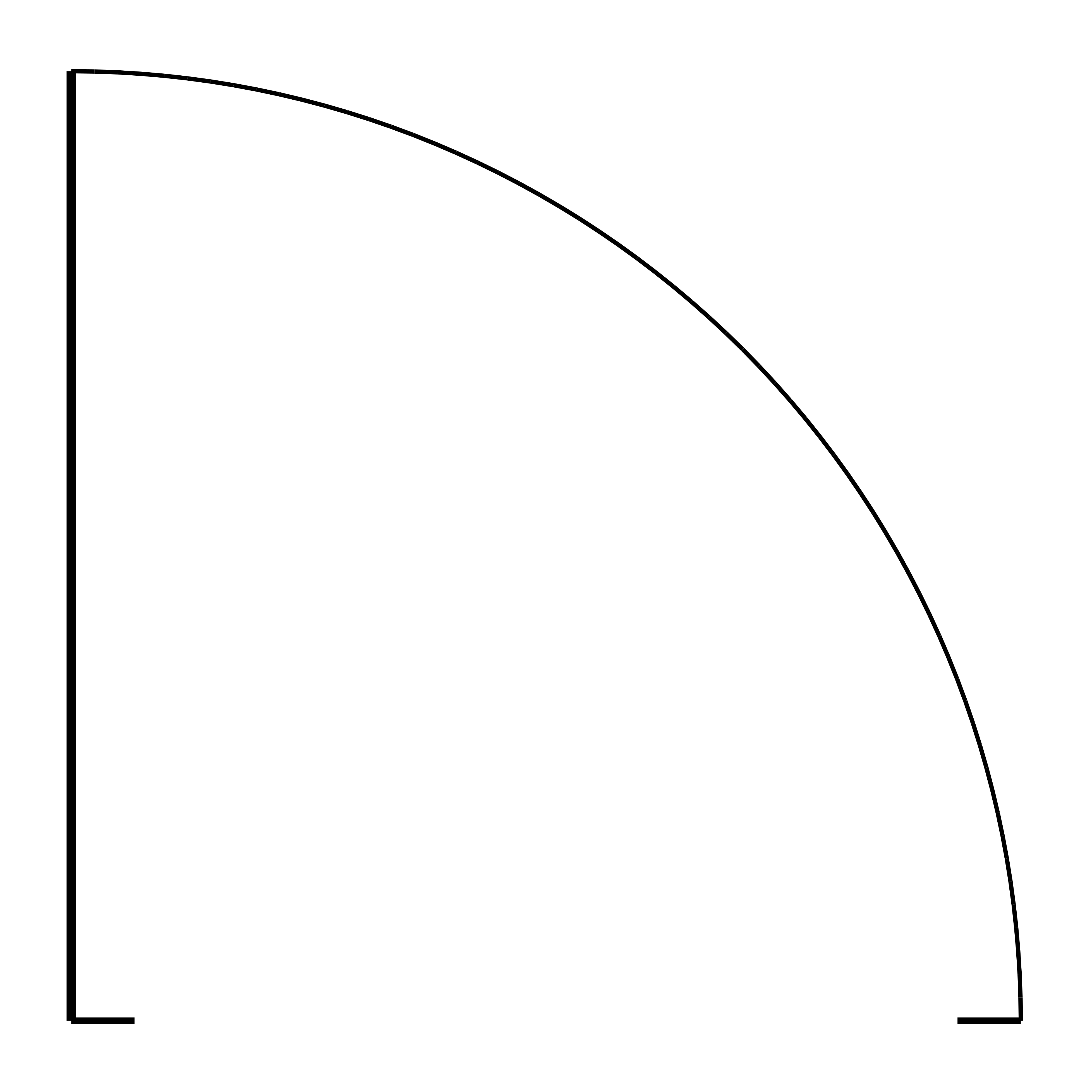
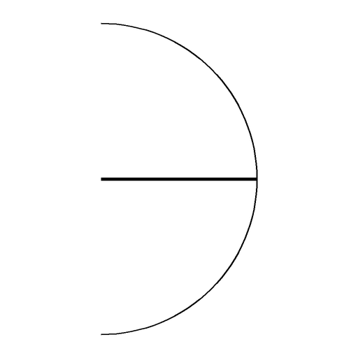
06 / DoorsSingle swing leftTypical / 900 mm opening; 900 mm leaves

True size model geometry
Typical size: 900 mm opening; 900 mm leaves.
Overall drawn extents: 900 × 900 mm / 35.433 × 35.433 in.

Swing envelopes and track zones are included in the overall geometry size.

Sizes are not code requirements. DXF layer: A-DOOR. Select import units explicitly and use insertion scale 1. SVG includes margin; PNG is fitted to a square transparent canvas.

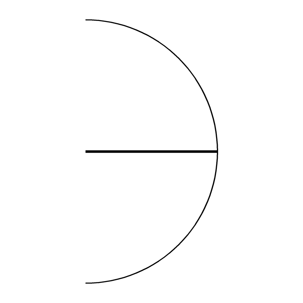
07 / DoorsSingle swing rightTypical / 900 mm opening; 900 mm leaves

True size model geometry
Typical size: 900 mm opening; 900 mm leaves.
Overall drawn extents: 900 × 900 mm / 35.433 × 35.433 in.

Swing envelopes and track zones are included in the overall geometry size.

Sizes are not code requirements. DXF layer: A-DOOR. Select import units explicitly and use insertion scale 1. SVG includes margin; PNG is fitted to a square transparent canvas.

08 / DoorsDouble acting doorTypical / 900 mm leaf; 1800 mm swing envelope

True size model geometry
Typical size: 900 mm leaf; 1800 mm swing envelope.
Overall drawn extents: 900 × 1800 mm / 35.433 × 70.866 in.

Swing envelopes and track zones are included in the overall geometry size.

Sizes are not code requirements. DXF layer: A-DOOR. Select import units explicitly and use insertion scale 1. SVG includes margin; PNG is fitted to a square transparent canvas.

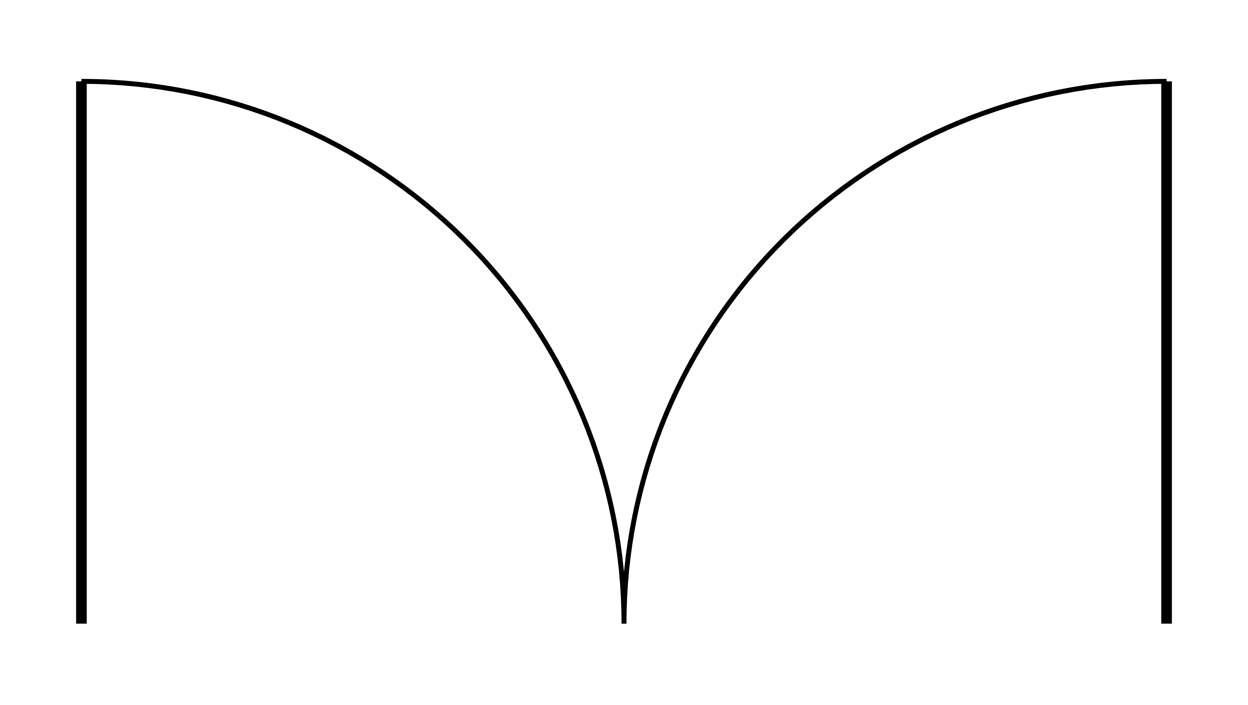
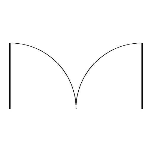
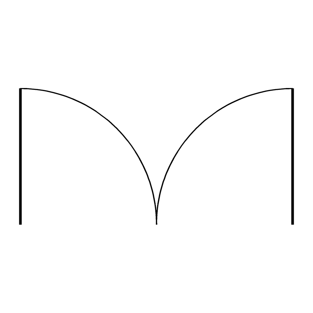
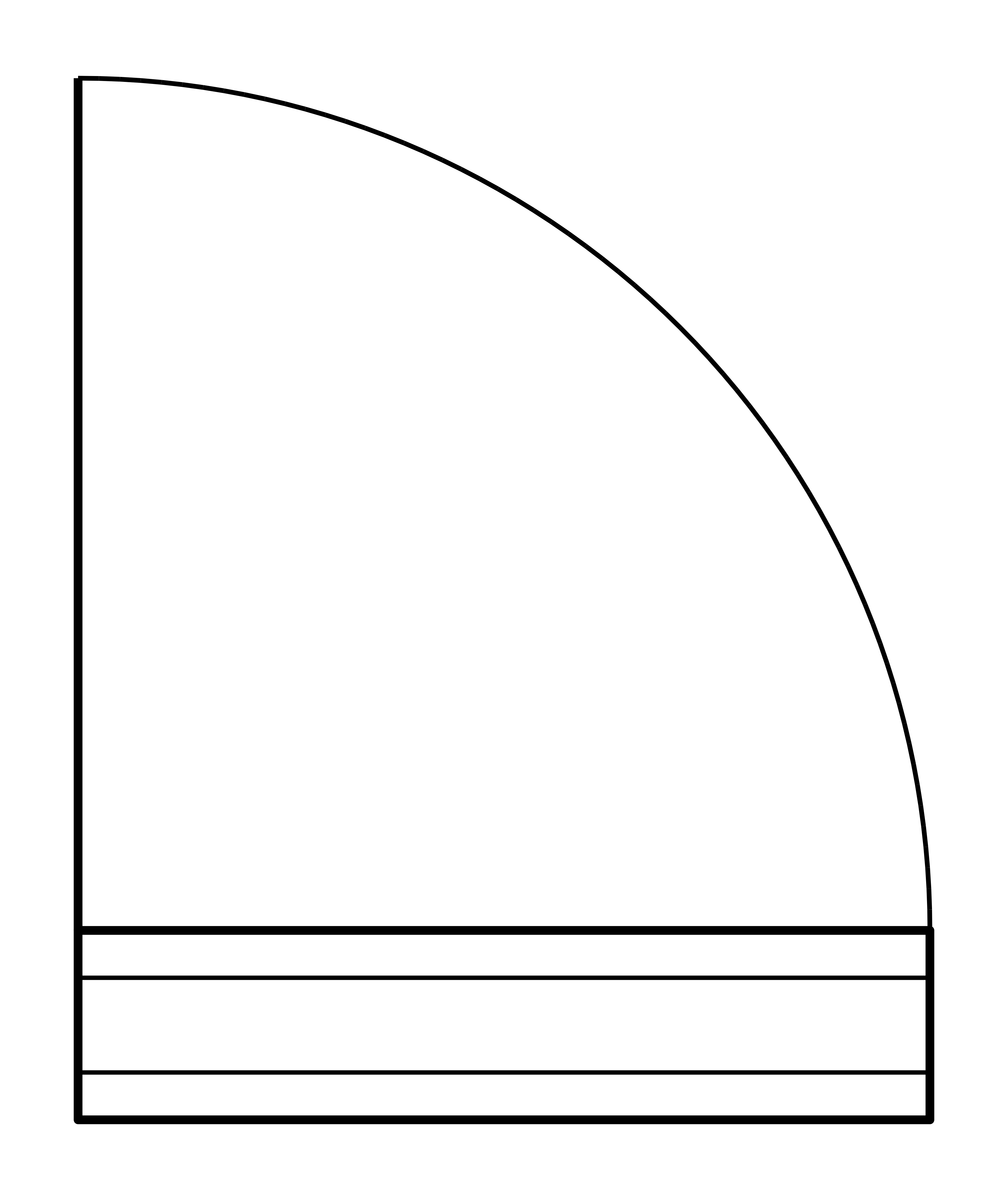
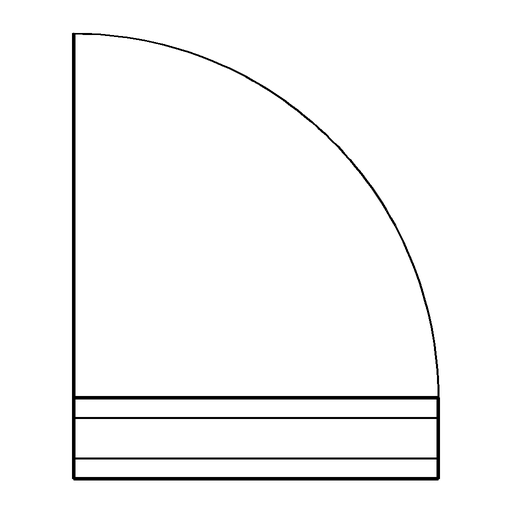
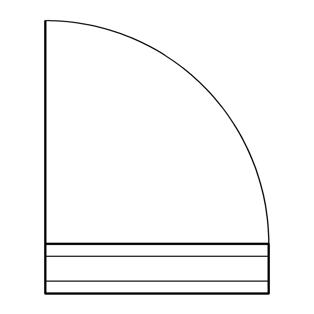
09 / DoorsDouble French doorTypical / 1800 mm opening; 900 mm leaves

True size model geometry
Typical size: 1800 mm opening; 900 mm leaves.
Overall drawn extents: 1800 × 900 mm / 70.866 × 35.433 in.

Swing envelopes and track zones are included in the overall geometry size.

Sizes are not code requirements. DXF layer: A-DOOR. Select import units explicitly and use insertion scale 1. SVG includes margin; PNG is fitted to a square transparent canvas.

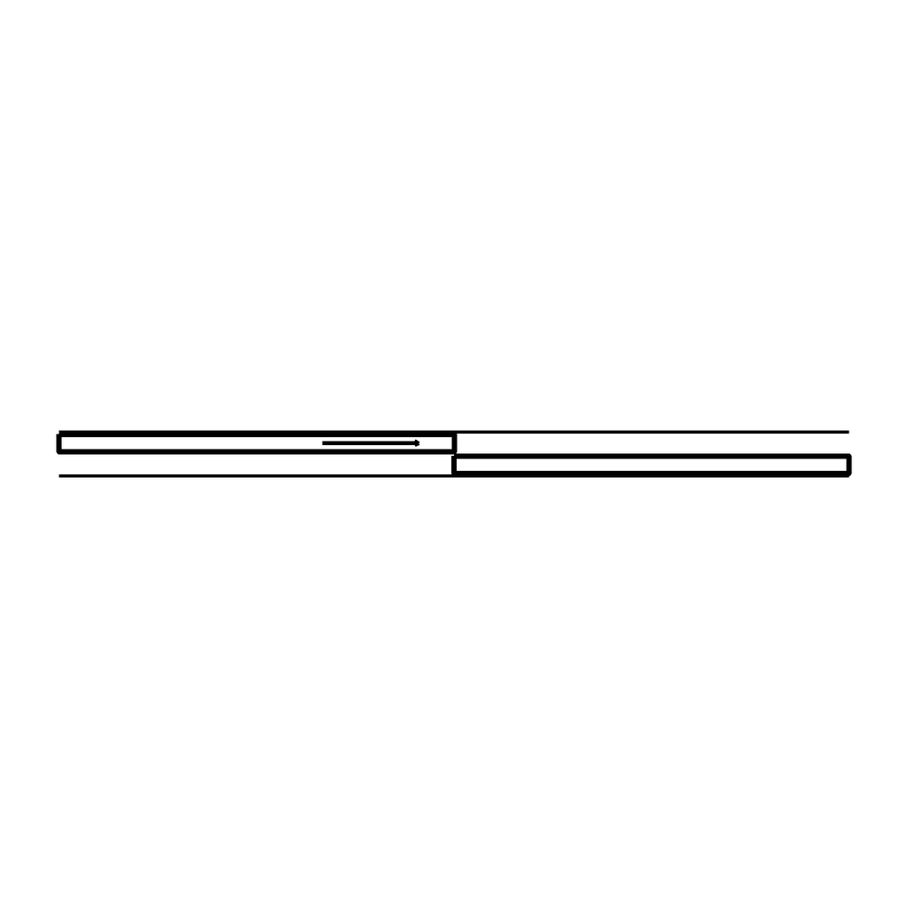
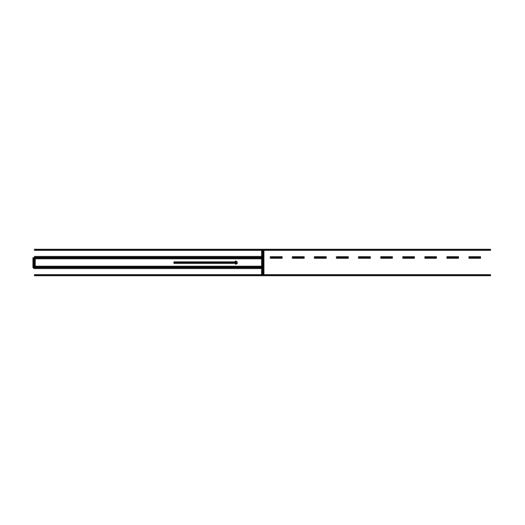
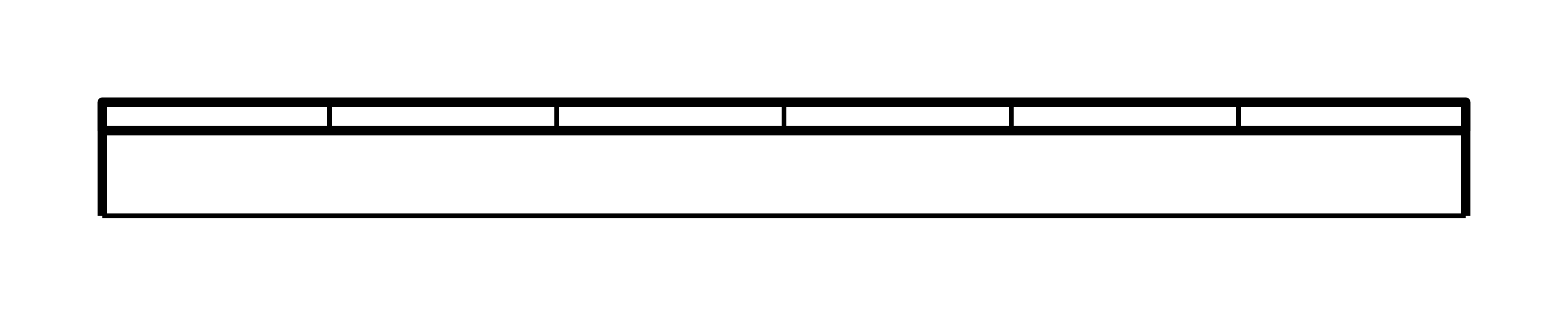
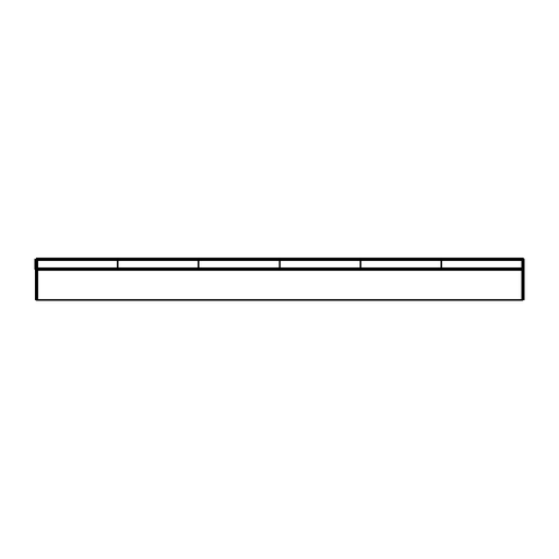
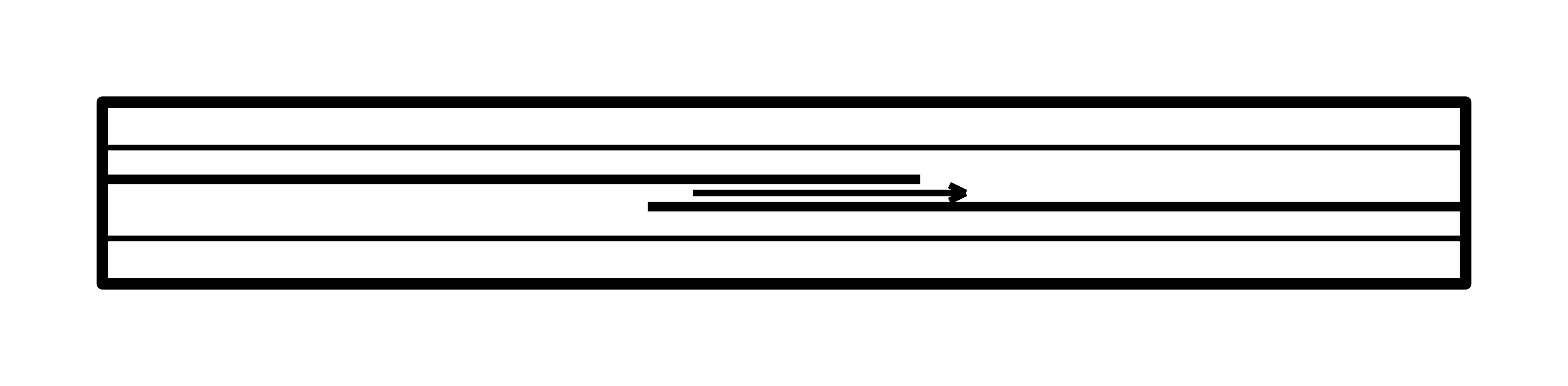
10 / DoorsSliding doorTypical / 1800 mm track; 900 mm leaves

True size model geometry
Typical size: 1800 mm track; 900 mm leaves.
Overall drawn extents: 1800 × 100 mm / 70.866 × 3.937 in.

Swing envelopes and track zones are included in the overall geometry size.

Sizes are not code requirements. DXF layer: A-DOOR. Select import units explicitly and use insertion scale 1. SVG includes margin; PNG is fitted to a square transparent canvas.

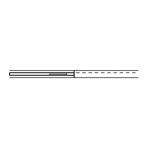
11 / DoorsPocket doorTypical / 900 mm opening; 900 mm pocket

True size model geometry
Typical size: 900 mm opening; 900 mm pocket.
Overall drawn extents: 1800 × 100 mm / 70.866 × 3.937 in.

Swing envelopes and track zones are included in the overall geometry size.

Sizes are not code requirements. DXF layer: A-DOOR. Select import units explicitly and use insertion scale 1. SVG includes margin; PNG is fitted to a square transparent canvas.

12 / DoorsBifold doorTypical / 1200 mm opening; 600 mm leaves

True size model geometry
Typical size: 1200 mm opening; 600 mm leaves.
Overall drawn extents: 1200 × 600 mm / 47.244 × 23.622 in.

Swing envelopes and track zones are included in the overall geometry size.

Sizes are not code requirements. DXF layer: A-DOOR. Select import units explicitly and use insertion scale 1. SVG includes margin; PNG is fitted to a square transparent canvas.

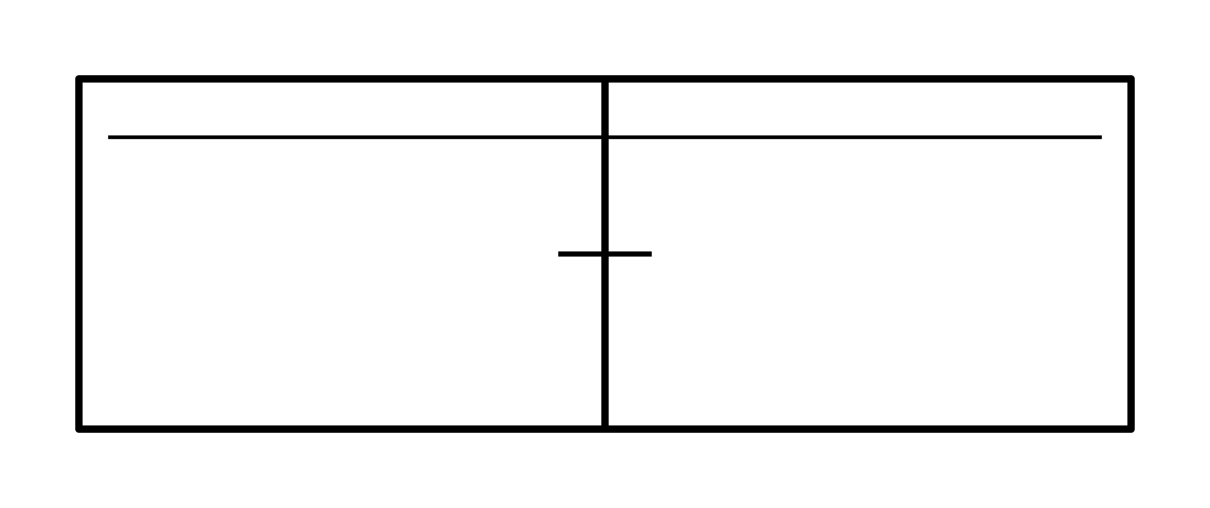
13 / DoorsBarn doorTypical / 2000 mm track; 1000 mm leaf

True size model geometry
Typical size: 2000 mm track; 1000 mm leaf.
Overall drawn extents: 2000 × 150 mm / 78.740 × 5.906 in.

Swing envelopes and track zones are included in the overall geometry size.

Sizes are not code requirements. DXF layer: A-DOOR. Select import units explicitly and use insertion scale 1. SVG includes margin; PNG is fitted to a square transparent canvas.

14 / DoorsOverhead garage doorTypical / 2400 mm opening; 200 mm track zone

True size model geometry
Typical size: 2400 mm opening; 200 mm track zone.
Overall drawn extents: 2400 × 200 mm / 94.488 × 7.874 in.

Swing envelopes and track zones are included in the overall geometry size.

Sizes are not code requirements. DXF layer: A-DOOR. Select import units explicitly and use insertion scale 1. SVG includes margin; PNG is fitted to a square transparent canvas.

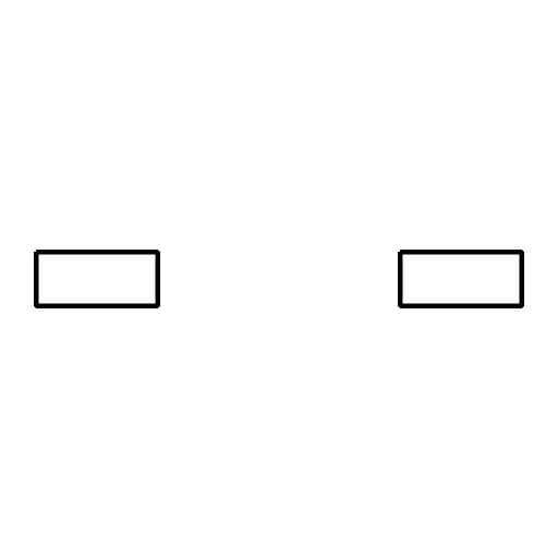
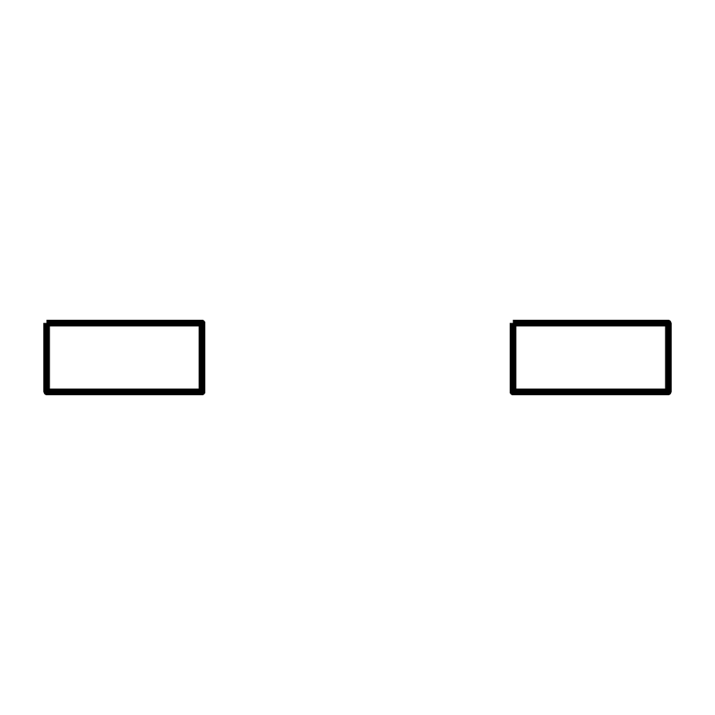
15 / WindowsFixed windowTypical / 1200 × 200 mm

True size model geometry
Typical size: 1200 × 200 mm.
Overall drawn extents: 1200 × 200 mm / 47.244 × 7.874 in.

Typical frame envelope, including sill and any sash swing.

Sizes are not code requirements. DXF layer: A-GLAZ. Select import units explicitly and use insertion scale 1. SVG includes margin; PNG is fitted to a square transparent canvas.

16 / WindowsCasement windowTypical / 900 mm frame; 900 mm sash swing; 200 mm sill

True size model geometry
Typical size: 900 mm frame; 900 mm sash swing; 200 mm sill.
Overall drawn extents: 900 × 1100 mm / 35.433 × 43.307 in.

Typical frame envelope, including sill and any sash swing.

Sizes are not code requirements. DXF layer: A-GLAZ. Select import units explicitly and use insertion scale 1. SVG includes margin; PNG is fitted to a square transparent canvas.

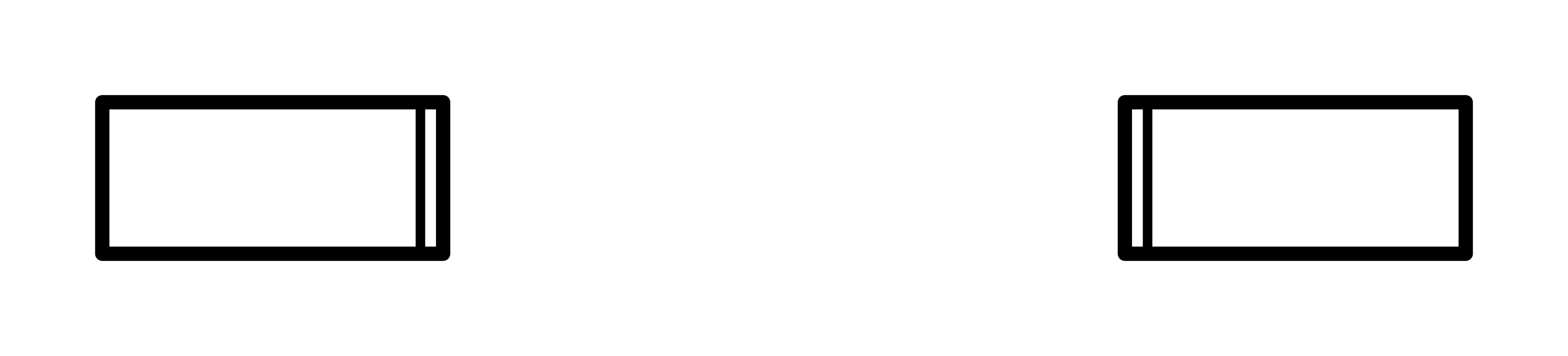
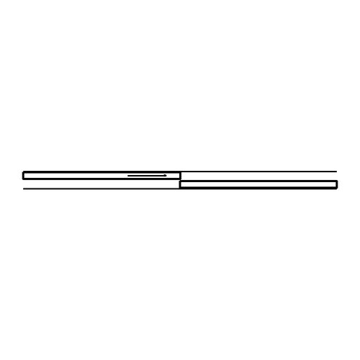
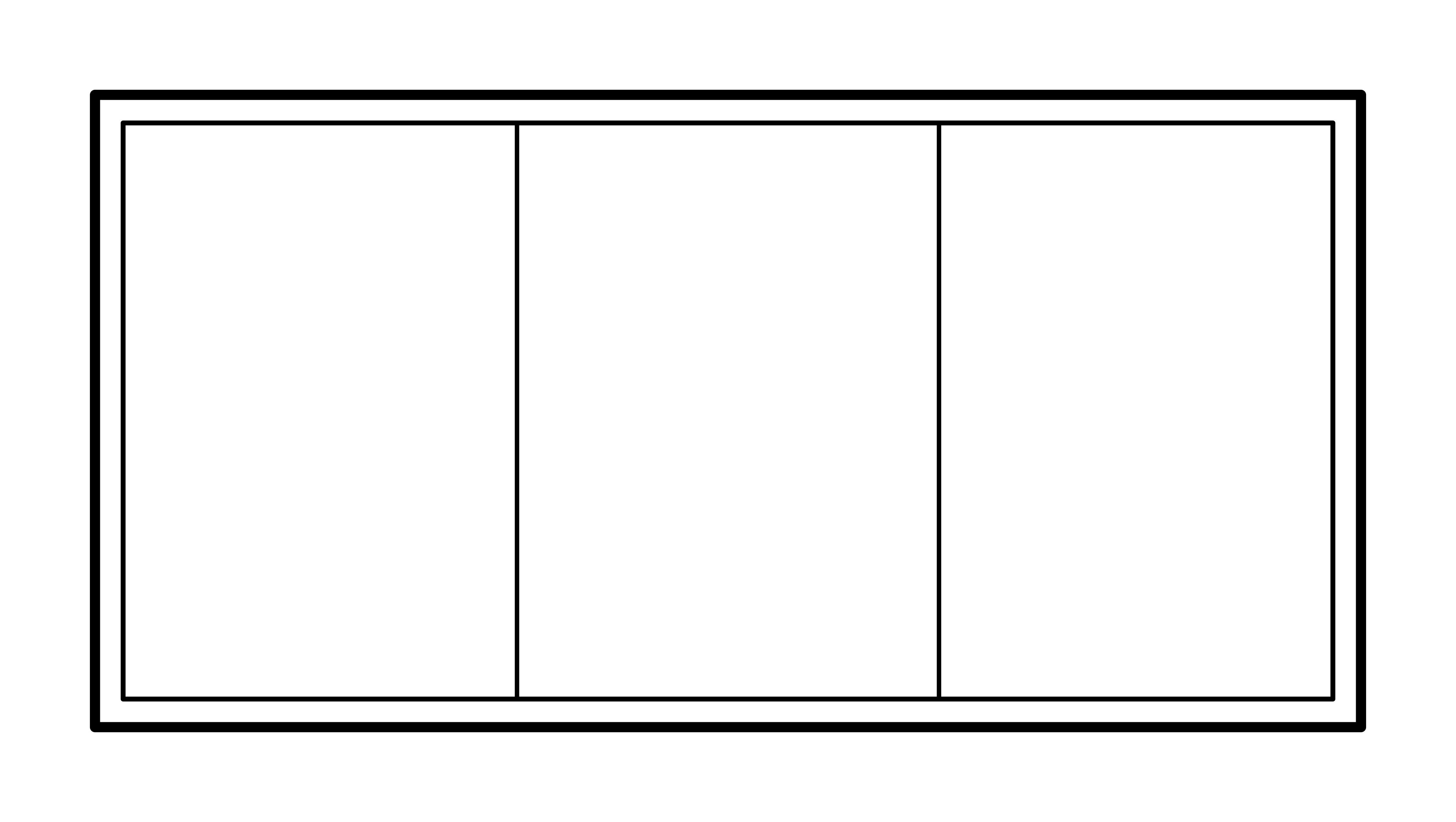
17 / WindowsSliding windowTypical / 1500 × 200 mm

True size model geometry
Typical size: 1500 × 200 mm.
Overall drawn extents: 1500 × 200 mm / 59.055 × 7.874 in.

Typical frame envelope, including sill and any sash swing.

Sizes are not code requirements. DXF layer: A-GLAZ. Select import units explicitly and use insertion scale 1. SVG includes margin; PNG is fitted to a square transparent canvas.

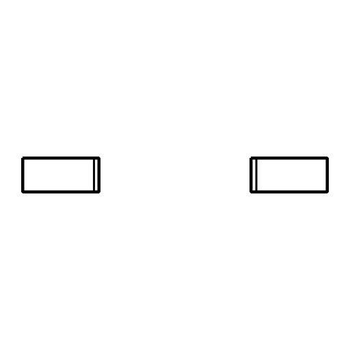
18 / WindowsDouble hung windowTypical / 900 × 200 mm

True size model geometry
Typical size: 900 × 200 mm.
Overall drawn extents: 900 × 200 mm / 35.433 × 7.874 in.

Typical frame envelope, including sill and any sash swing.

Sizes are not code requirements. DXF layer: A-GLAZ. Select import units explicitly and use insertion scale 1. SVG includes margin; PNG is fitted to a square transparent canvas.

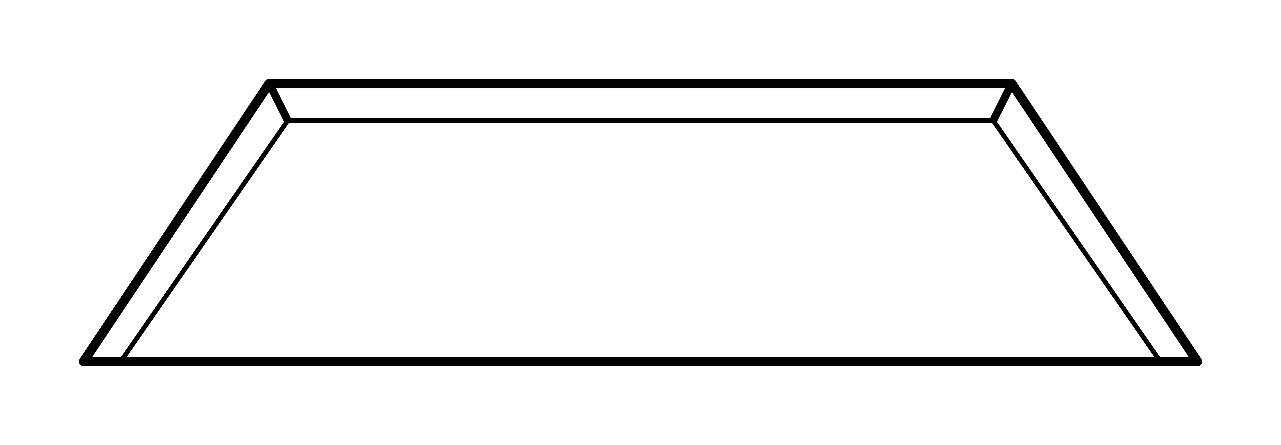
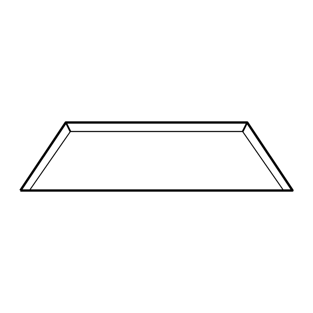
19 / WindowsBay windowTypical / 2400 × 600 mm

True size model geometry
Typical size: 2400 × 600 mm.
Overall drawn extents: 2400 × 600 mm / 94.488 × 23.622 in.

Typical frame envelope, including sill and any sash swing.

Sizes are not code requirements. DXF layer: A-GLAZ. Select import units explicitly and use insertion scale 1. SVG includes margin; PNG is fitted to a square transparent canvas.

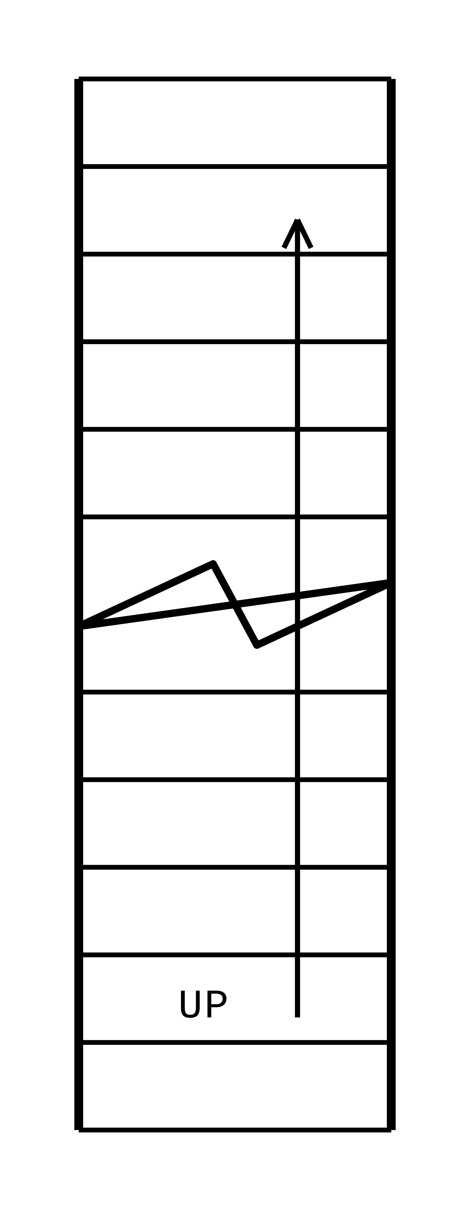
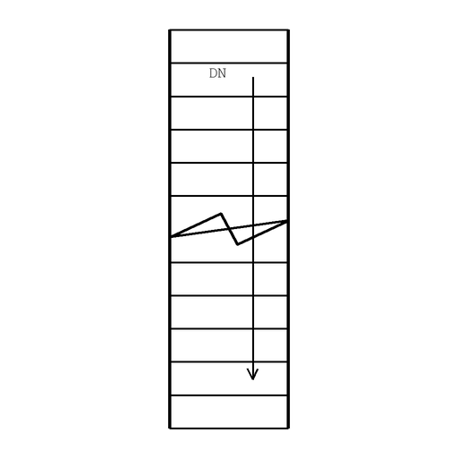
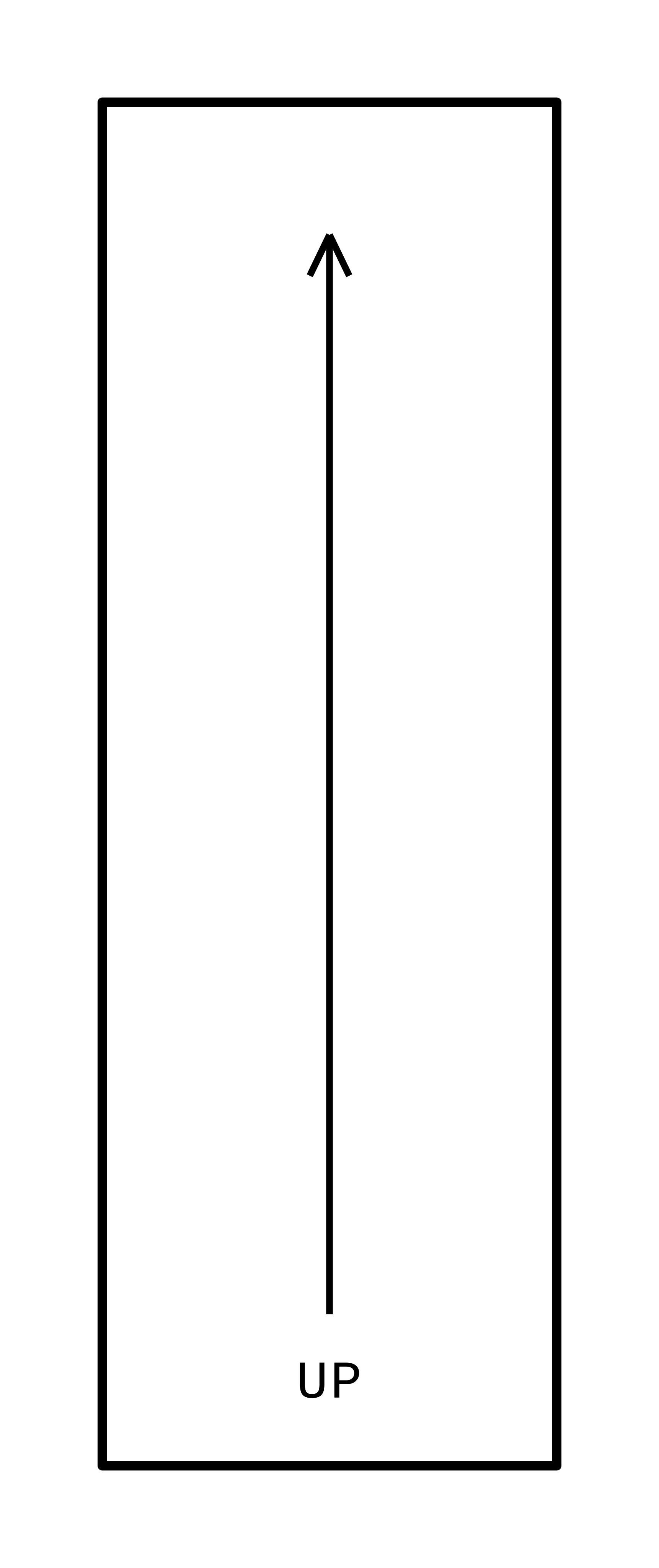
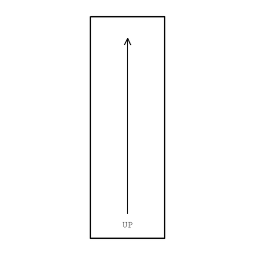
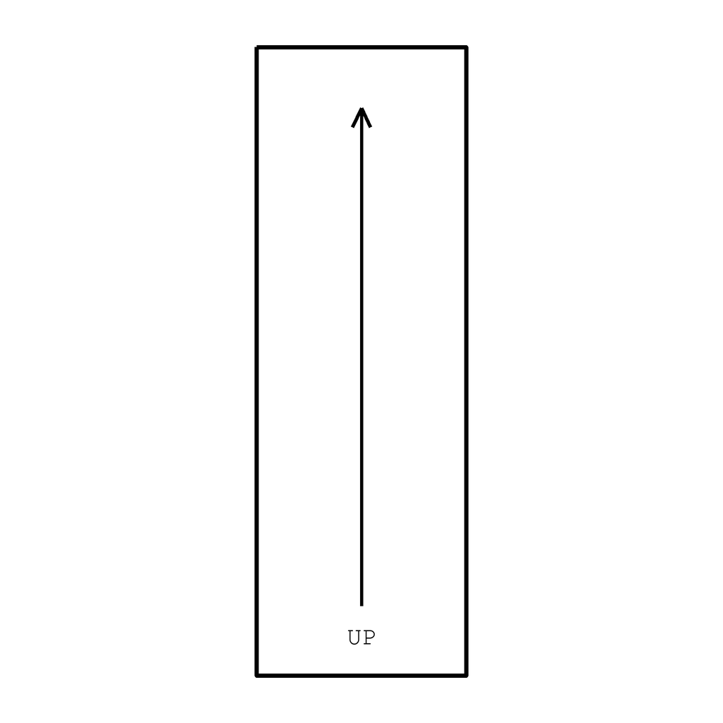
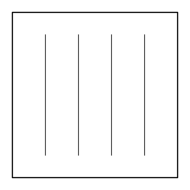
20 / Stairs and levelsStraight stair UPTypical / 1000 × 3360 mm

True size model geometry
Typical size: 1000 × 3360 mm.
Overall drawn extents: 1000 × 3360 mm / 39.370 × 132.283 in.

Typical plan envelope. Treads are diagrammatic; design the rise, run and clearances for your project.

Sizes are not code requirements. DXF layer: A-STAIR. Select import units explicitly and use insertion scale 1. SVG includes margin; PNG is fitted to a square transparent canvas.

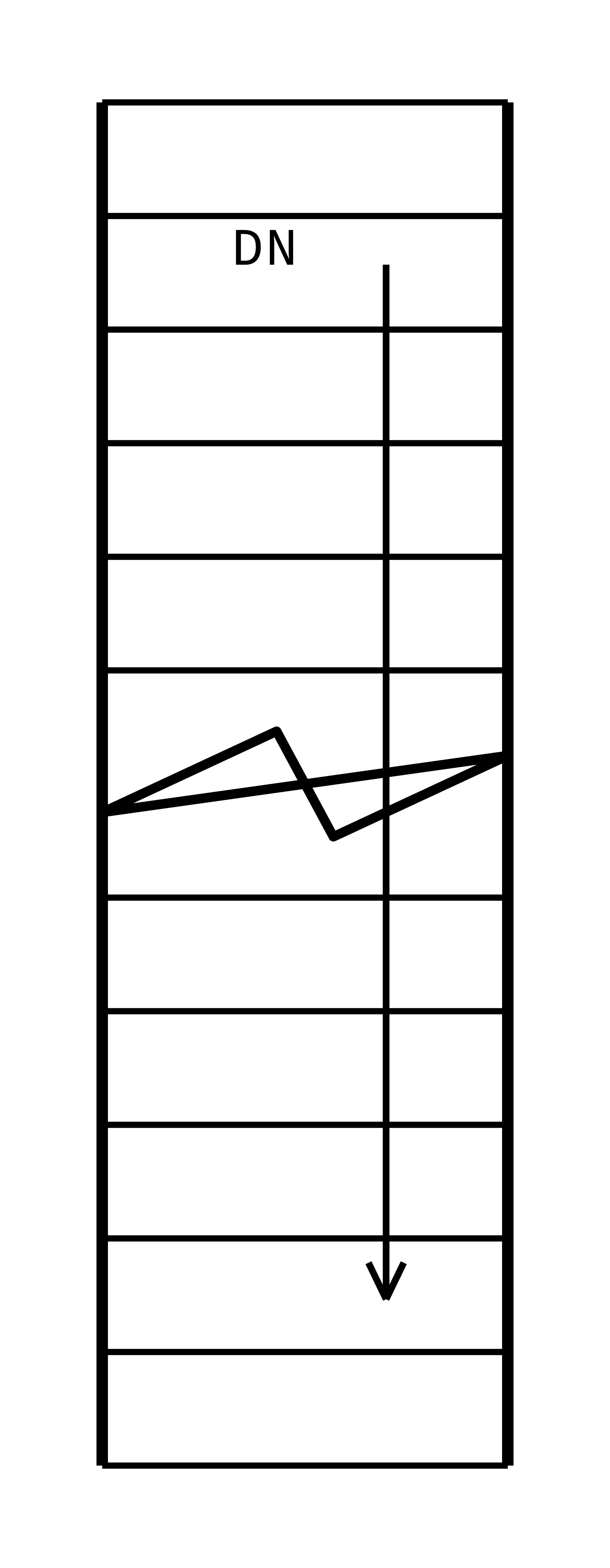
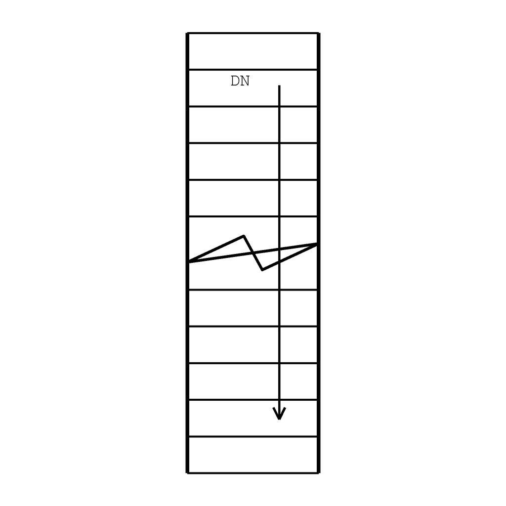
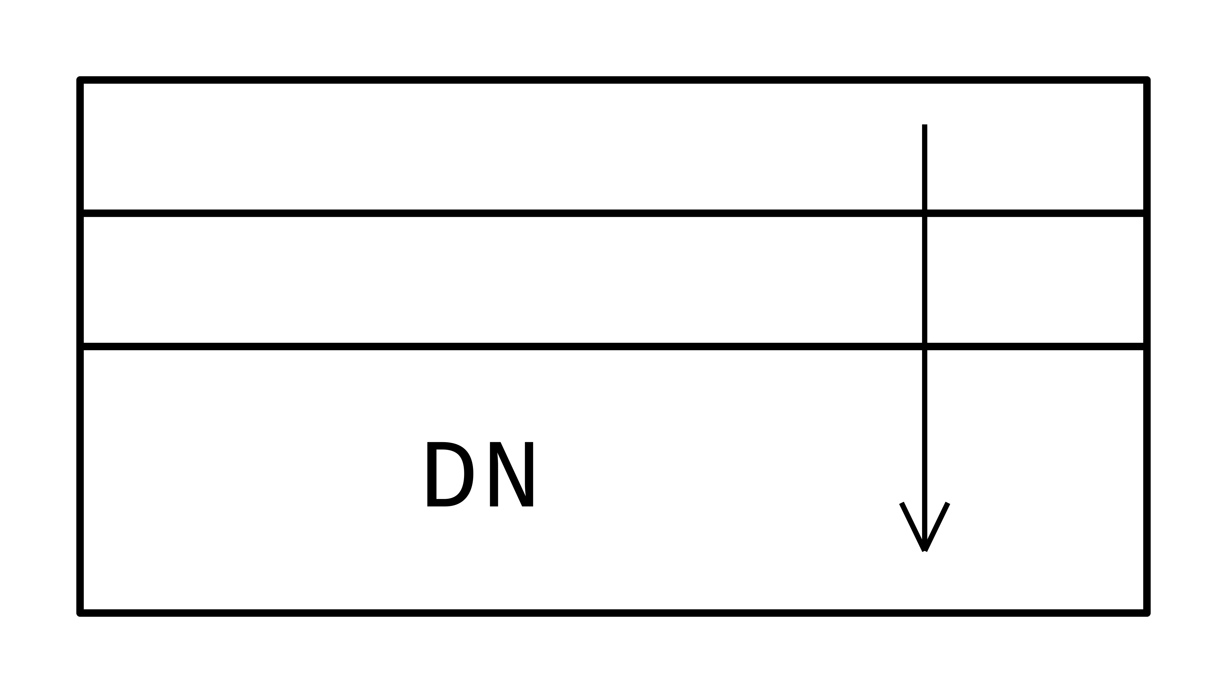
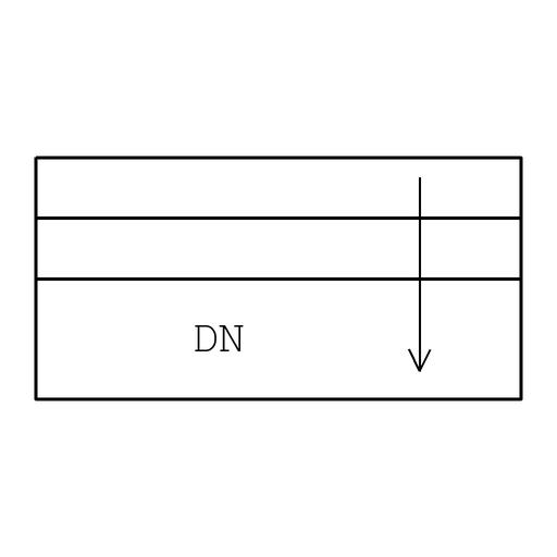
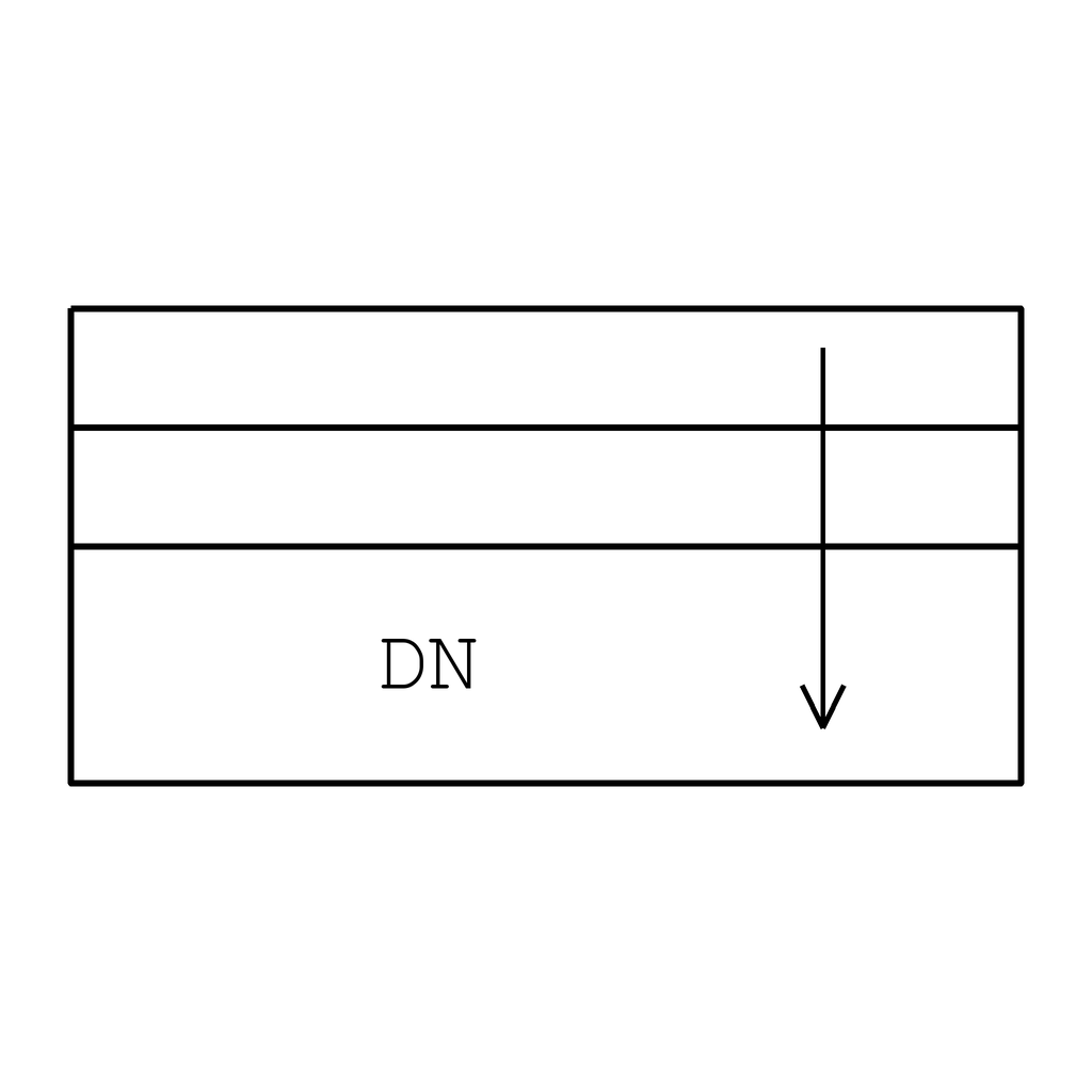
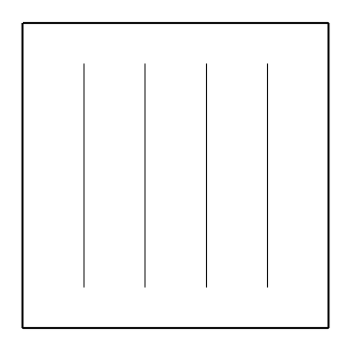
21 / Stairs and levelsStraight stair DNTypical / 1000 × 3360 mm

True size model geometry
Typical size: 1000 × 3360 mm.
Overall drawn extents: 1000 × 3360 mm / 39.370 × 132.283 in.

Typical plan envelope. Treads are diagrammatic; design the rise, run and clearances for your project.

Sizes are not code requirements. DXF layer: A-STAIR. Select import units explicitly and use insertion scale 1. SVG includes margin; PNG is fitted to a square transparent canvas.

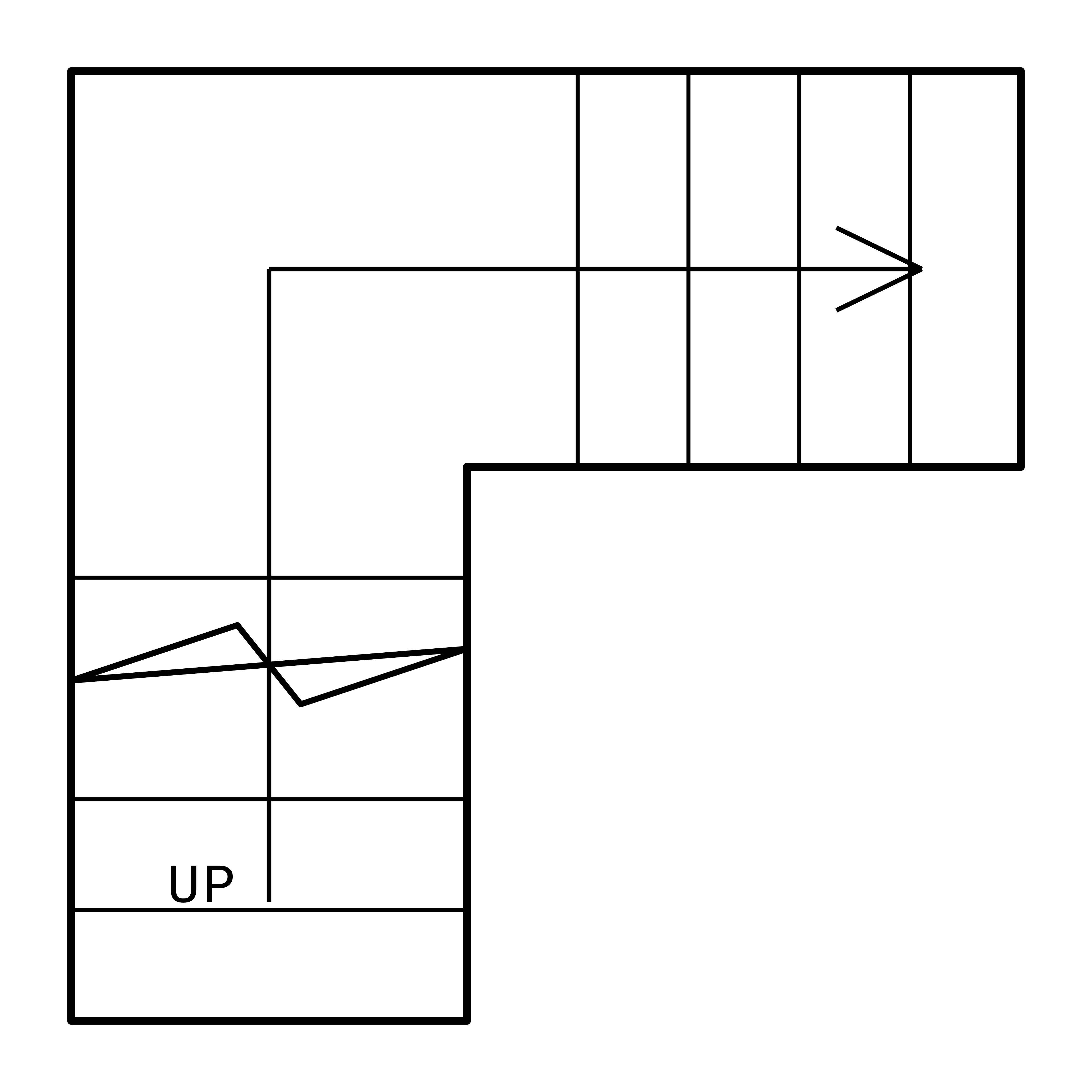
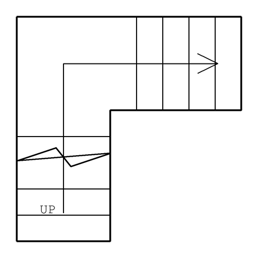
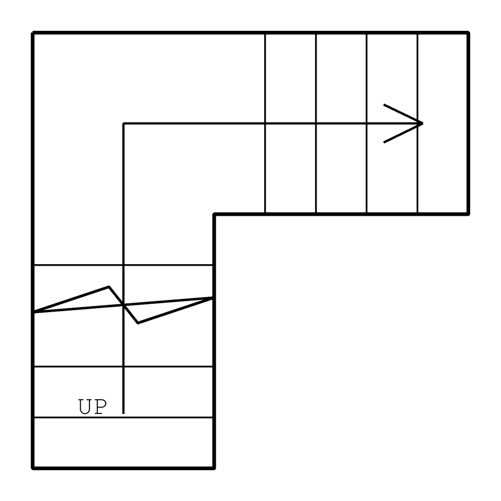
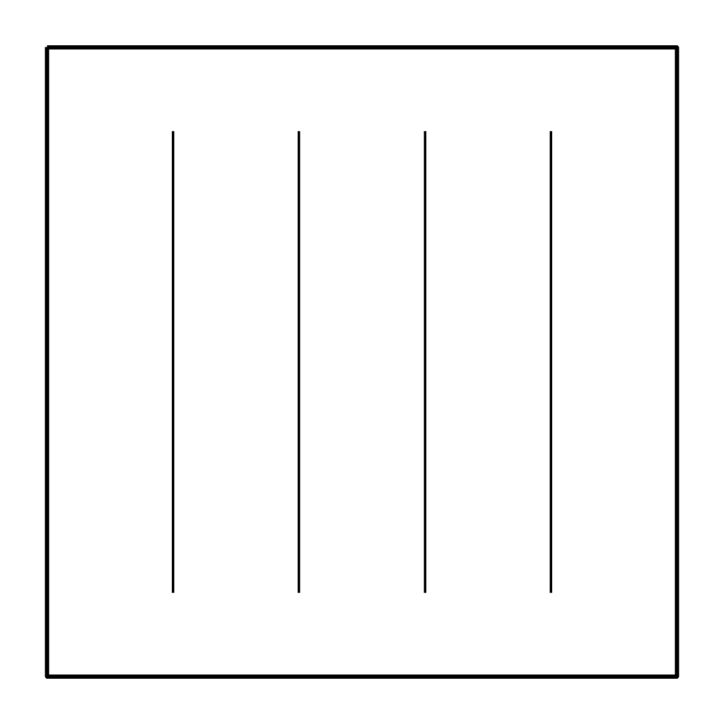
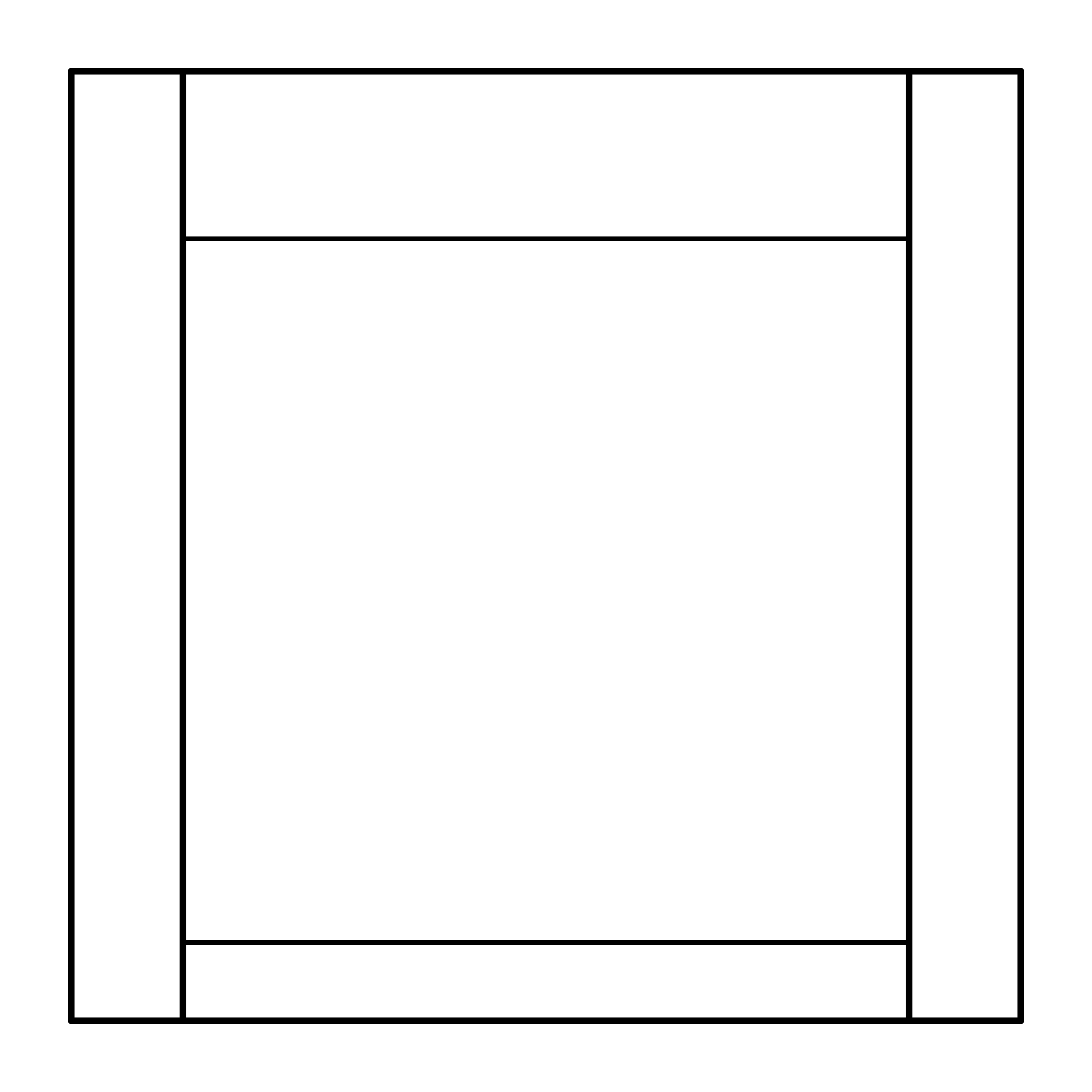
22 / Stairs and levelsL shaped stairTypical / 2400 × 2400 mm

True size model geometry
Typical size: 2400 × 2400 mm.
Overall drawn extents: 2400 × 2400 mm / 94.488 × 94.488 in.

Typical plan envelope. Treads are diagrammatic; design the rise, run and clearances for your project.

Sizes are not code requirements. DXF layer: A-STAIR. Select import units explicitly and use insertion scale 1. SVG includes margin; PNG is fitted to a square transparent canvas.

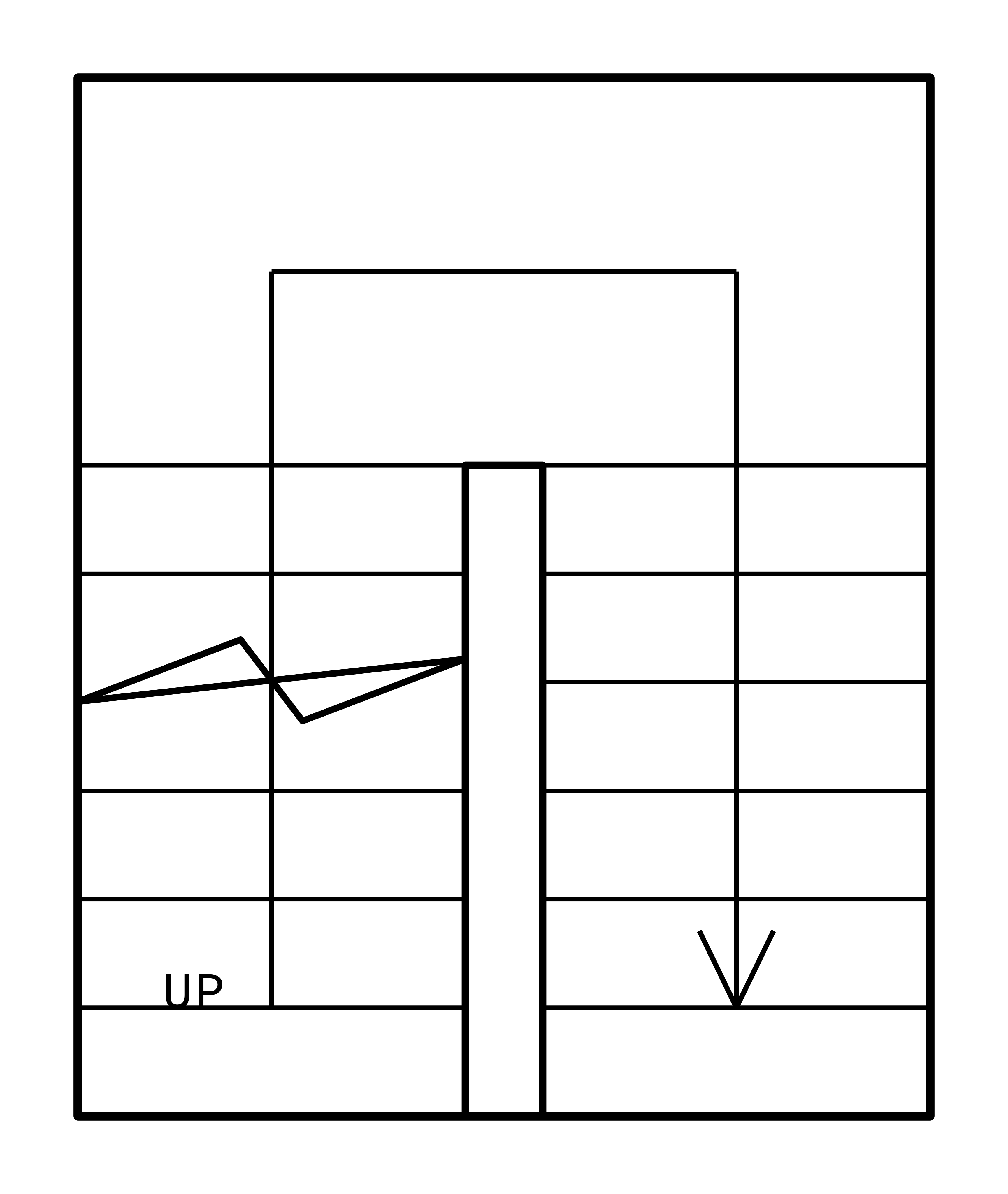
23 / Stairs and levelsU shaped stairTypical / 2200 × 2680 mm

True size model geometry
Typical size: 2200 × 2680 mm.
Overall drawn extents: 2200 × 2680 mm / 86.614 × 105.512 in.

Typical plan envelope. Treads are diagrammatic; design the rise, run and clearances for your project.

Sizes are not code requirements. DXF layer: A-STAIR. Select import units explicitly and use insertion scale 1. SVG includes margin; PNG is fitted to a square transparent canvas.

24 / Stairs and levelsSpiral stairTypical / 1800 × 1800 mm

True size model geometry
Typical size: 1800 × 1800 mm.
Overall drawn extents: 1800 × 1800 mm / 70.866 × 70.866 in.

Typical plan envelope. Treads are diagrammatic; design the rise, run and clearances for your project.

Sizes are not code requirements. DXF layer: A-STAIR. Select import units explicitly and use insertion scale 1. SVG includes margin; PNG is fitted to a square transparent canvas.

25 / Stairs and levelsRampTypical / 1200 × 3600 mm

True size model geometry
Typical size: 1200 × 3600 mm.
Overall drawn extents: 1200 × 3600 mm / 47.244 × 141.732 in.

Typical plan envelope. Treads are diagrammatic; design the rise, run and clearances for your project.

Sizes are not code requirements. DXF layer: A-STAIR. Select import units explicitly and use insertion scale 1. SVG includes margin; PNG is fitted to a square transparent canvas.

26 / Stairs and levelsStep downTypical / 1200 × 600 mm

True size model geometry
Typical size: 1200 × 600 mm.
Overall drawn extents: 1200 × 600 mm / 47.244 × 23.622 in.

Typical plan envelope. Treads are diagrammatic; design the rise, run and clearances for your project.

Sizes are not code requirements. DXF layer: A-STAIR. Select import units explicitly and use insertion scale 1. SVG includes margin; PNG is fitted to a square transparent canvas.

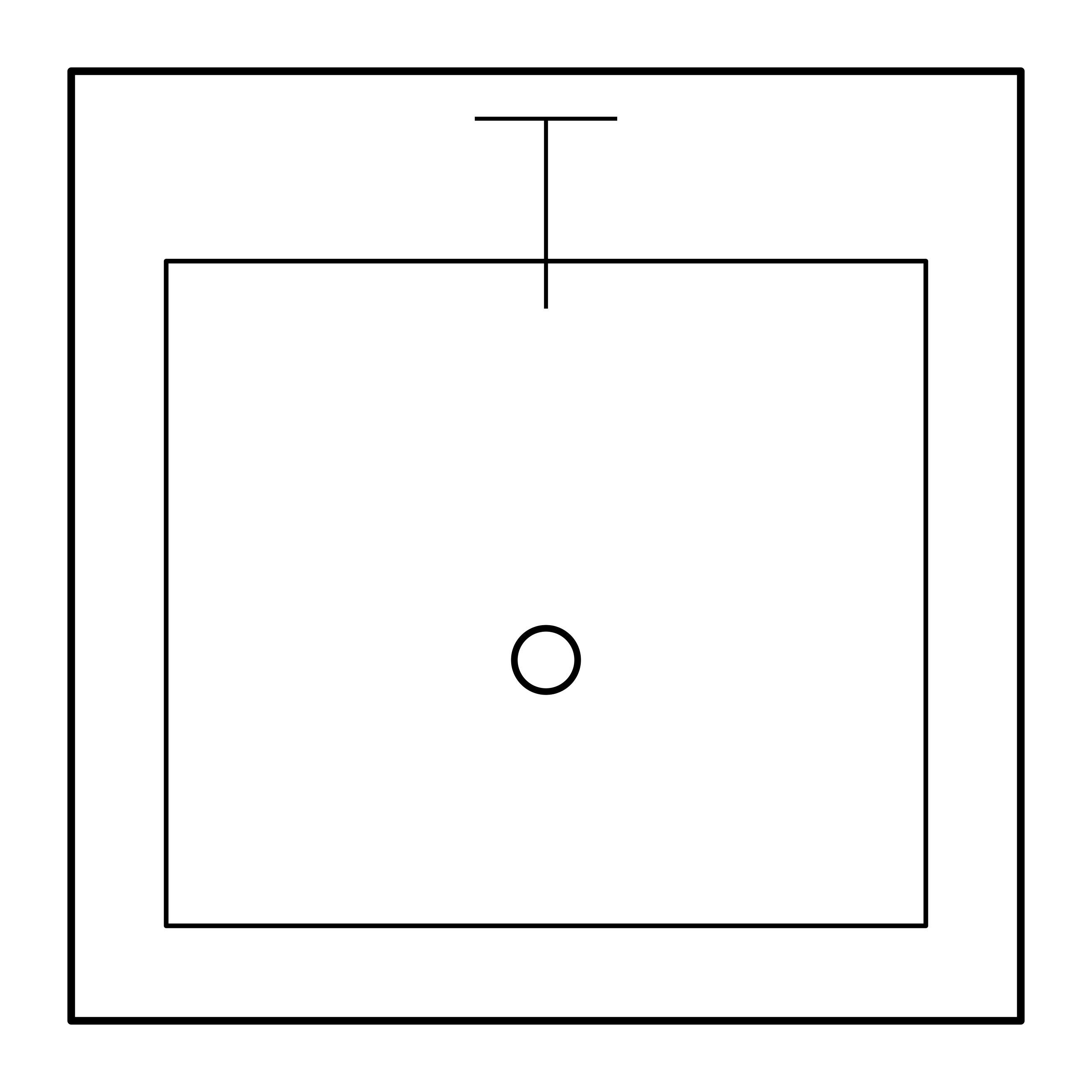
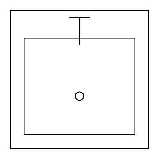
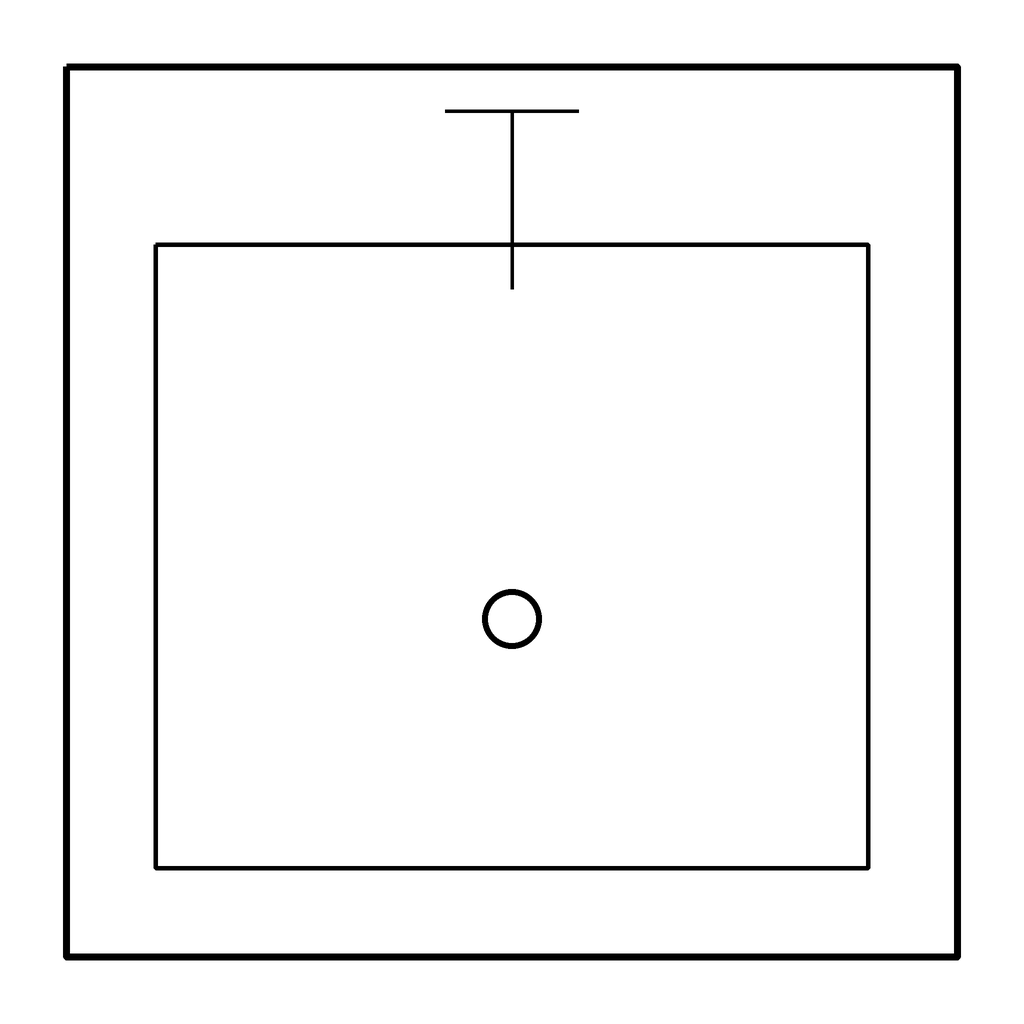
27 / KitchenSingle sinkTypical / 600 × 600 mm

True size model geometry
Typical size: 600 × 600 mm.
Overall drawn extents: 600 × 600 mm / 23.622 × 23.622 in.

Typical nominal dimensions; check your selected product and project clearances.

Sizes are not code requirements. DXF layer: A-FLOR-FIXT. Select import units explicitly and use insertion scale 1. SVG includes margin; PNG is fitted to a square transparent canvas.

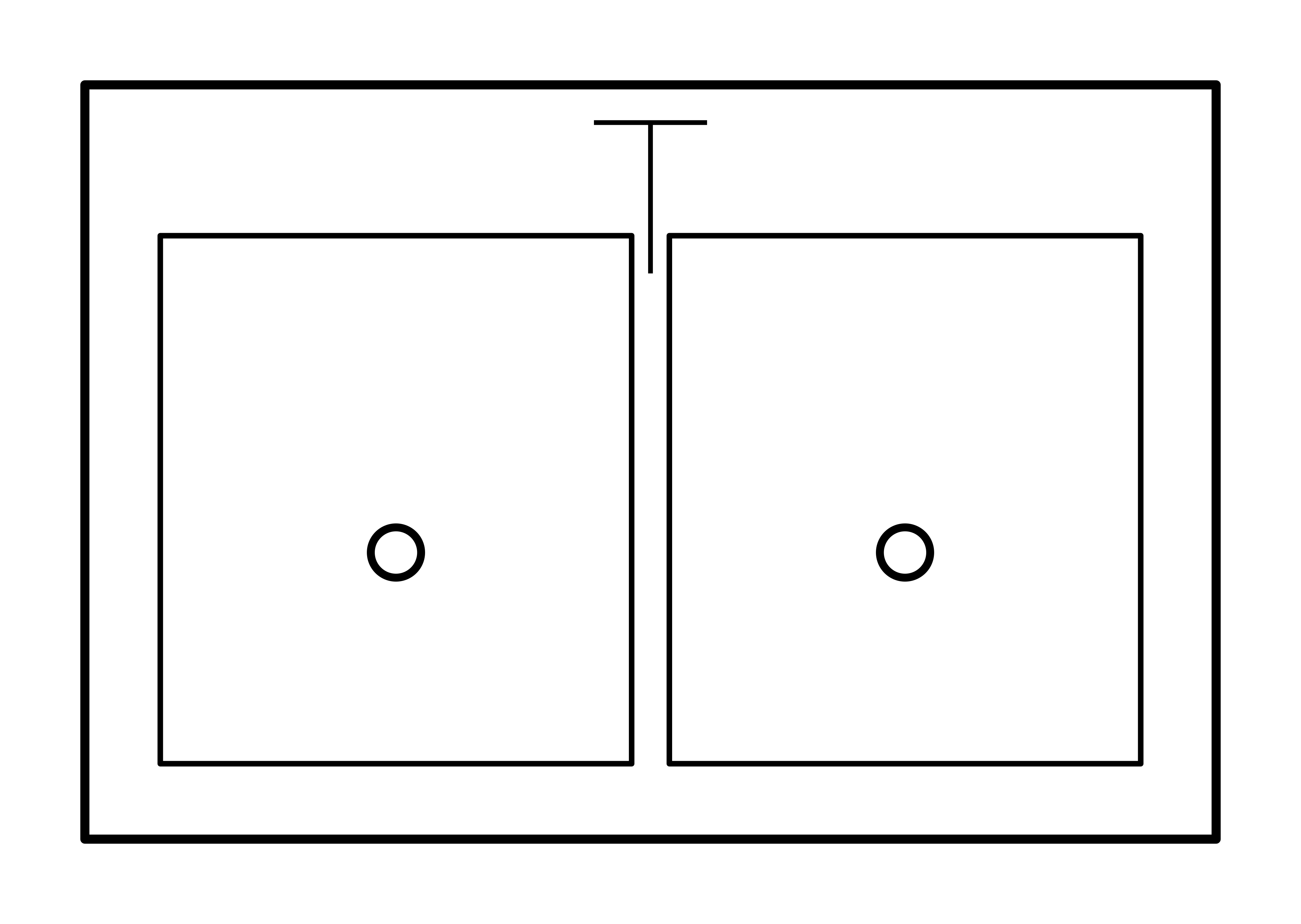
28 / KitchenDouble sinkTypical / 900 × 600 mm

True size model geometry
Typical size: 900 × 600 mm.
Overall drawn extents: 900 × 600 mm / 35.433 × 23.622 in.

Typical nominal dimensions; check your selected product and project clearances.

Sizes are not code requirements. DXF layer: A-FLOR-FIXT. Select import units explicitly and use insertion scale 1. SVG includes margin; PNG is fitted to a square transparent canvas.

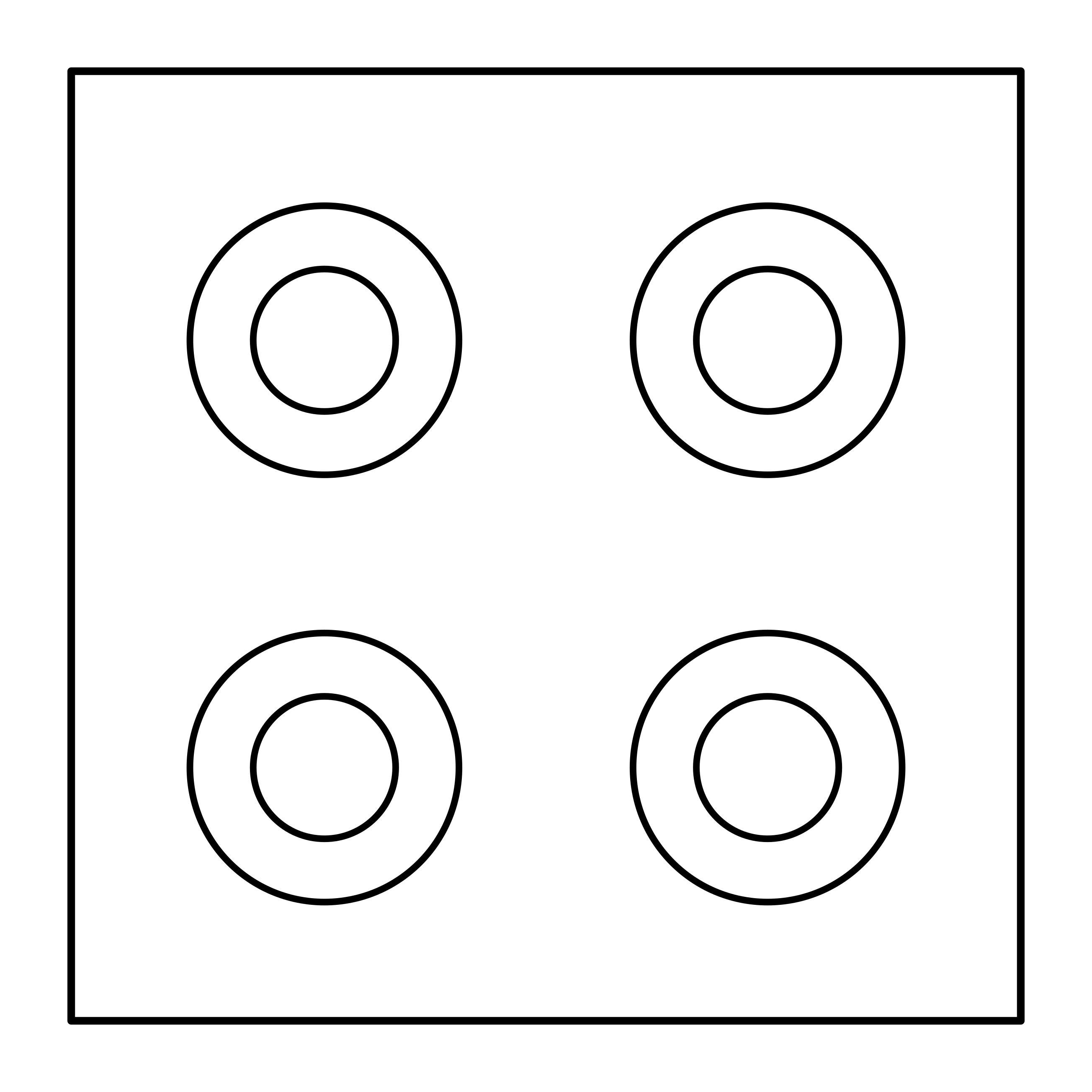
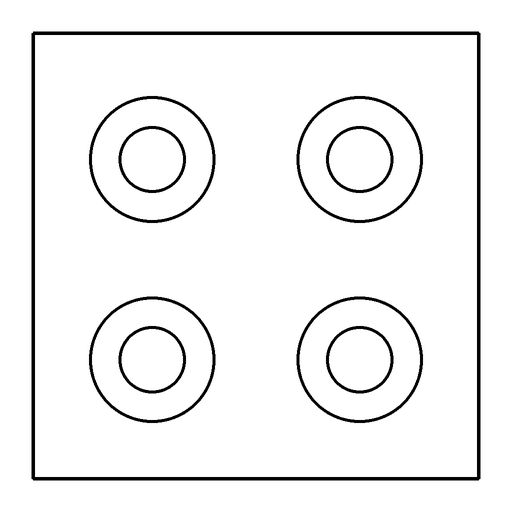
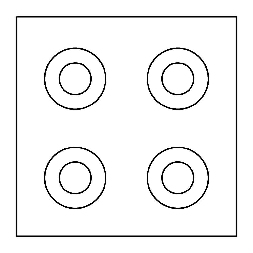
29 / KitchenRange cooktopTypical / 600 × 600 mm

True size model geometry
Typical size: 600 × 600 mm.
Overall drawn extents: 600 × 600 mm / 23.622 × 23.622 in.

Typical nominal dimensions; check your selected product and project clearances.

Sizes are not code requirements. DXF layer: A-FLOR-FIXT. Select import units explicitly and use insertion scale 1. SVG includes margin; PNG is fitted to a square transparent canvas.

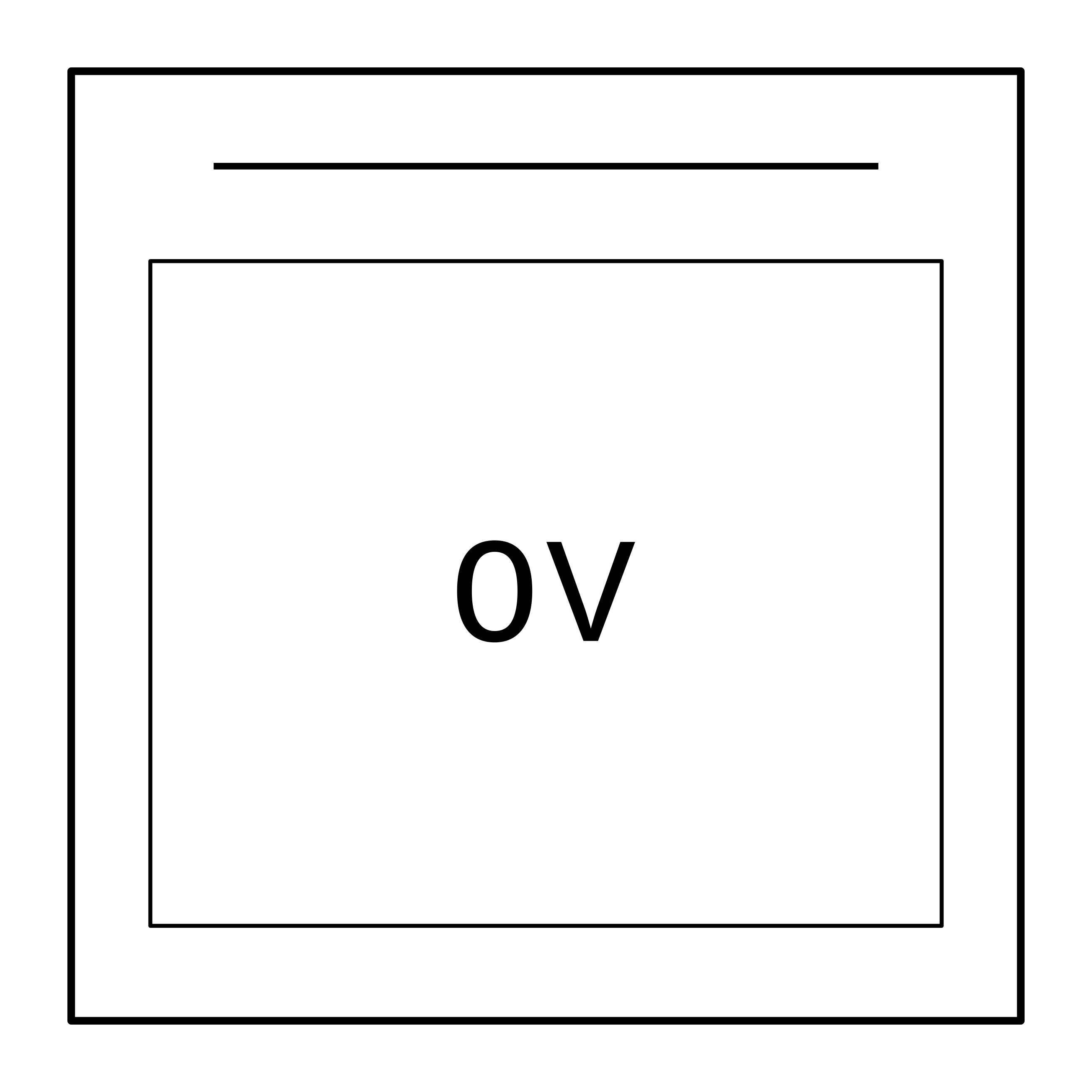
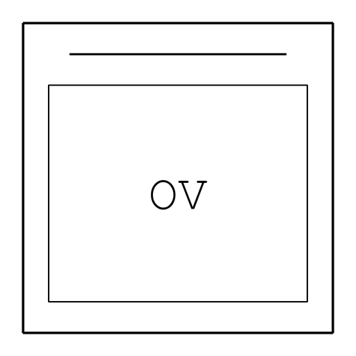
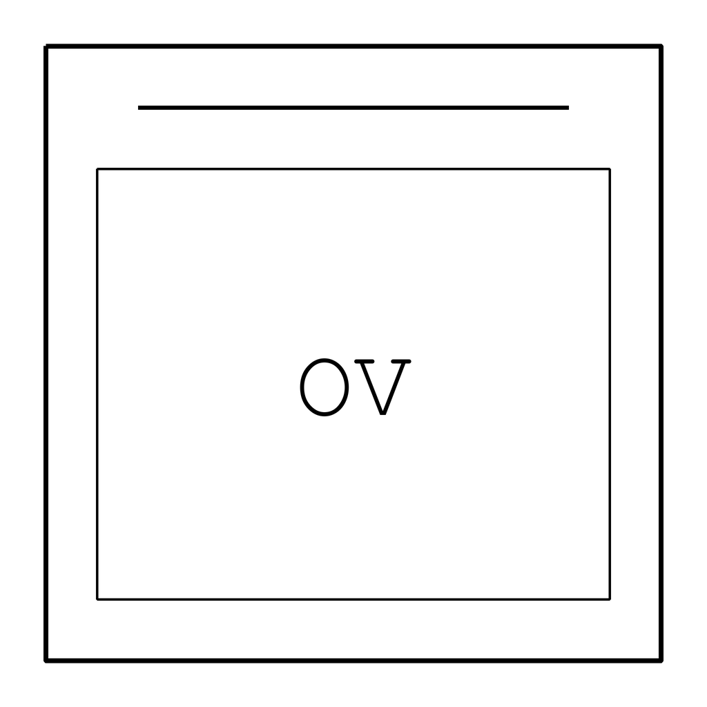
30 / KitchenOvenTypical / 600 × 600 mm

True size model geometry
Typical size: 600 × 600 mm.
Overall drawn extents: 600 × 600 mm / 23.622 × 23.622 in.

Typical nominal dimensions; check your selected product and project clearances.

Sizes are not code requirements. DXF layer: A-FLOR-FIXT. Select import units explicitly and use insertion scale 1. SVG includes margin; PNG is fitted to a square transparent canvas.

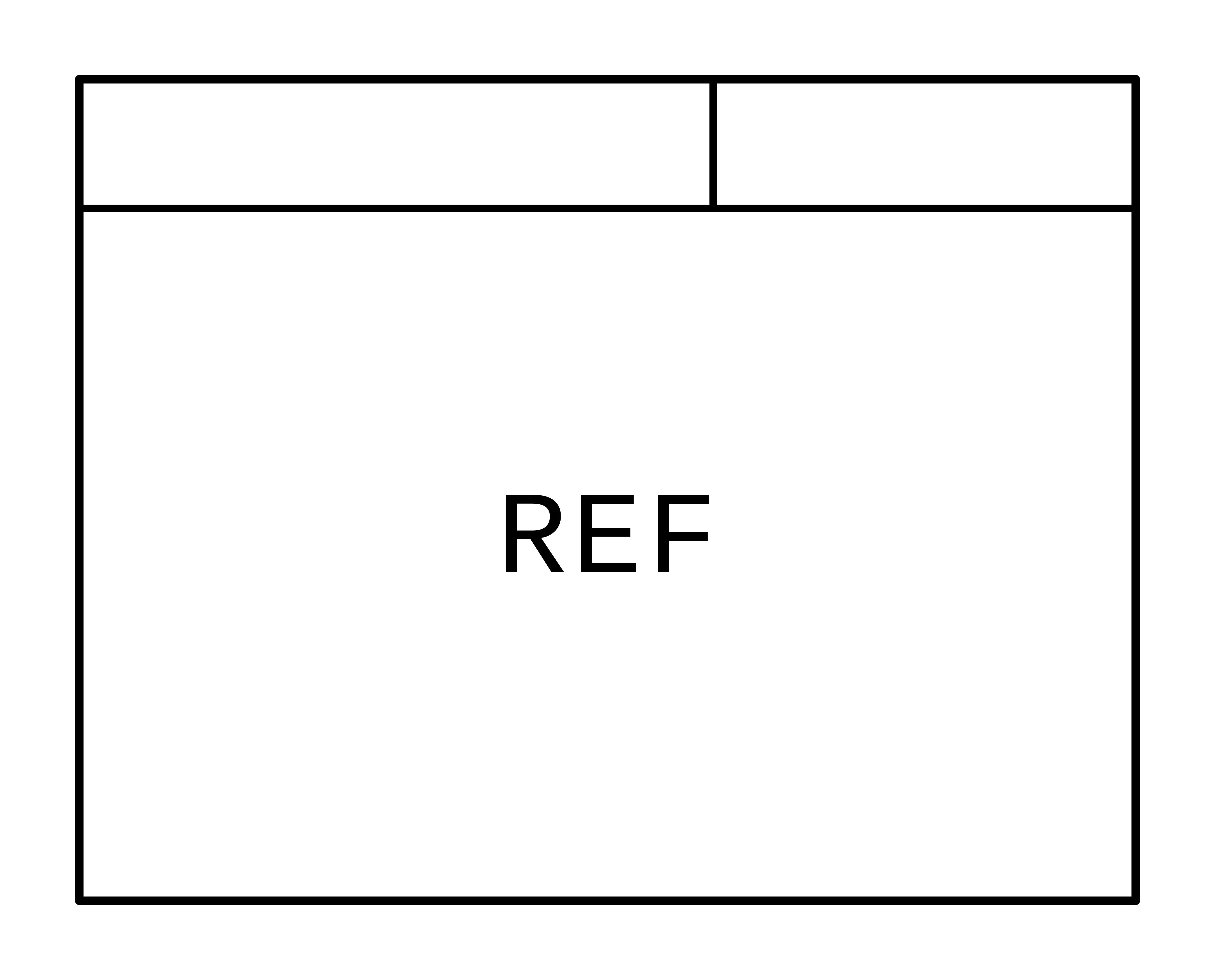
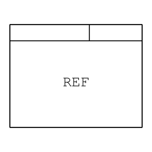
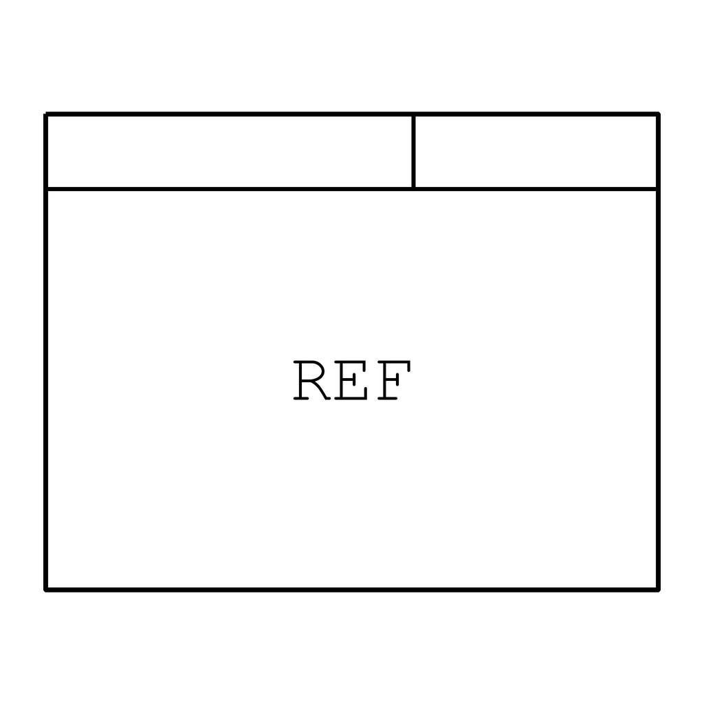
31 / KitchenRefrigeratorTypical / 900 × 700 mm

True size model geometry
Typical size: 900 × 700 mm.
Overall drawn extents: 900 × 700 mm / 35.433 × 27.559 in.

Typical nominal dimensions; check your selected product and project clearances.

Sizes are not code requirements. DXF layer: A-FLOR-FIXT. Select import units explicitly and use insertion scale 1. SVG includes margin; PNG is fitted to a square transparent canvas.

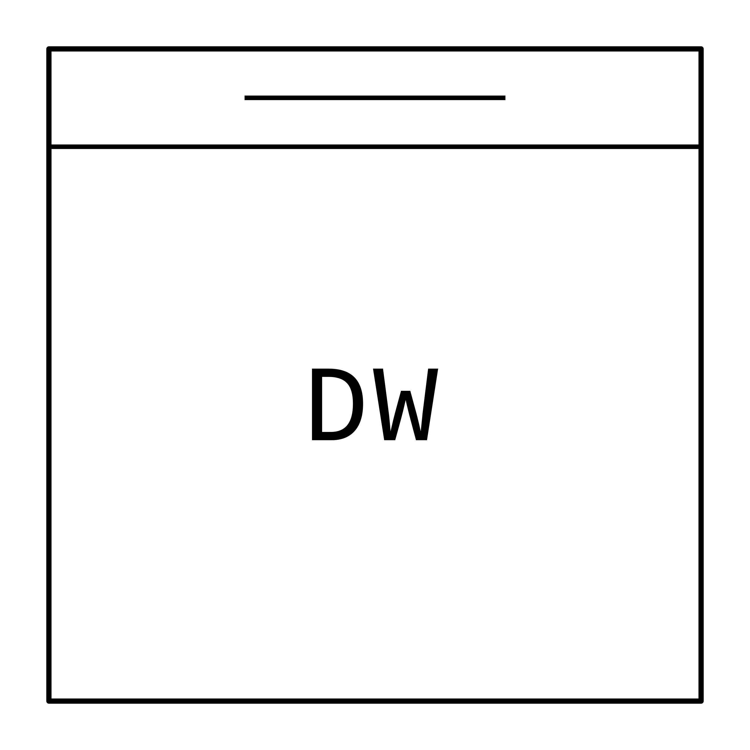
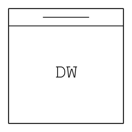
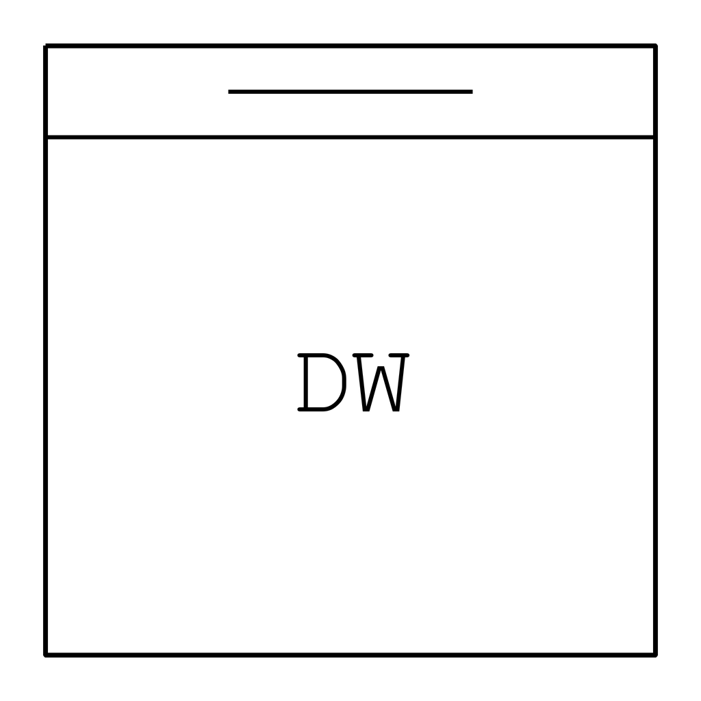
32 / KitchenDishwasherTypical / 600 × 600 mm

True size model geometry
Typical size: 600 × 600 mm.
Overall drawn extents: 600 × 600 mm / 23.622 × 23.622 in.

Typical nominal dimensions; check your selected product and project clearances.

Sizes are not code requirements. DXF layer: A-FLOR-FIXT. Select import units explicitly and use insertion scale 1. SVG includes margin; PNG is fitted to a square transparent canvas.

33 / KitchenKitchen islandTypical / 1800 × 900 mm

True size model geometry
Typical size: 1800 × 900 mm.
Overall drawn extents: 1800 × 900 mm / 70.866 × 35.433 in.

Typical nominal dimensions; check your selected product and project clearances.

Sizes are not code requirements. DXF layer: A-FLOR-FIXT. Select import units explicitly and use insertion scale 1. SVG includes margin; PNG is fitted to a square transparent canvas.

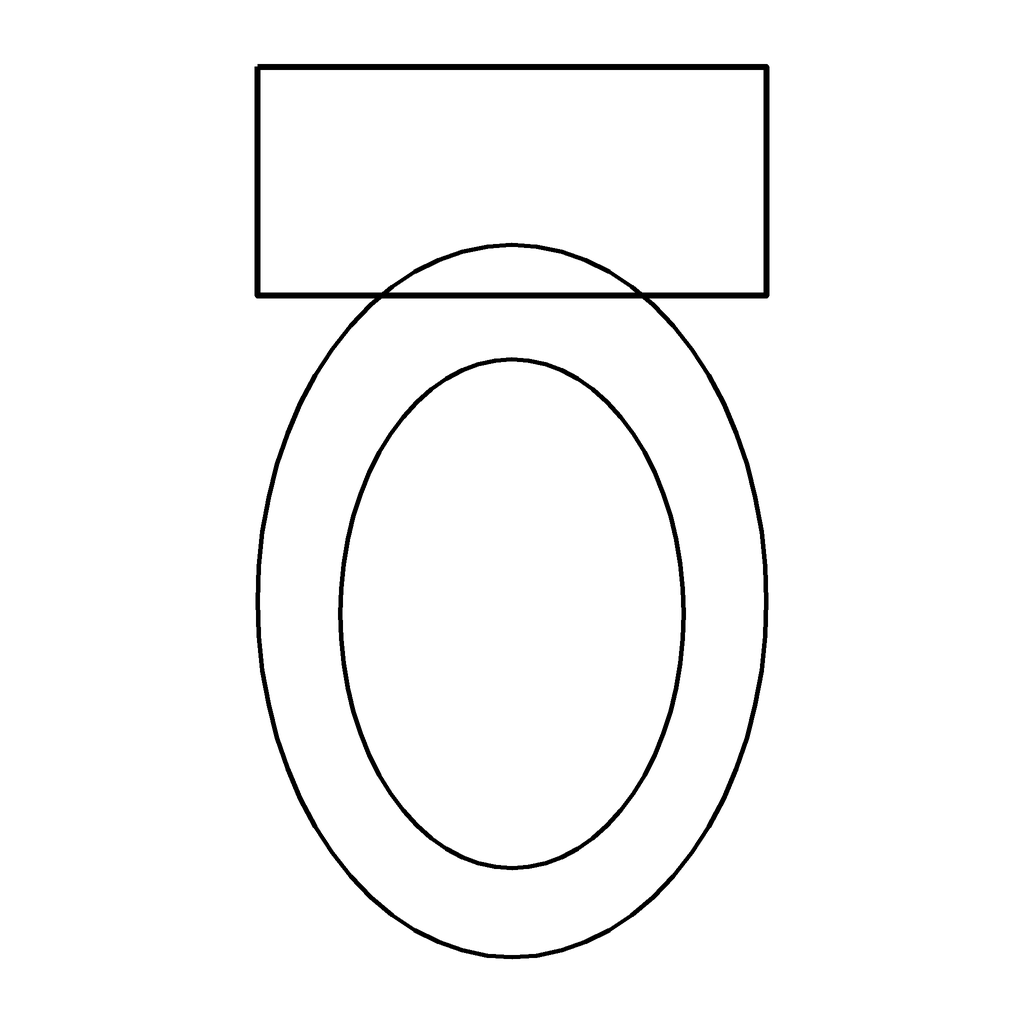
34 / BathroomWCTypical / 400 × 700 mm

True size model geometry
Typical size: 400 × 700 mm.
Overall drawn extents: 400 × 700 mm / 15.748 × 27.559 in.

Typical nominal dimensions; check your selected product and project clearances.

Sizes are not code requirements. DXF layer: A-FLOR-FIXT. Select import units explicitly and use insertion scale 1. SVG includes margin; PNG is fitted to a square transparent canvas.

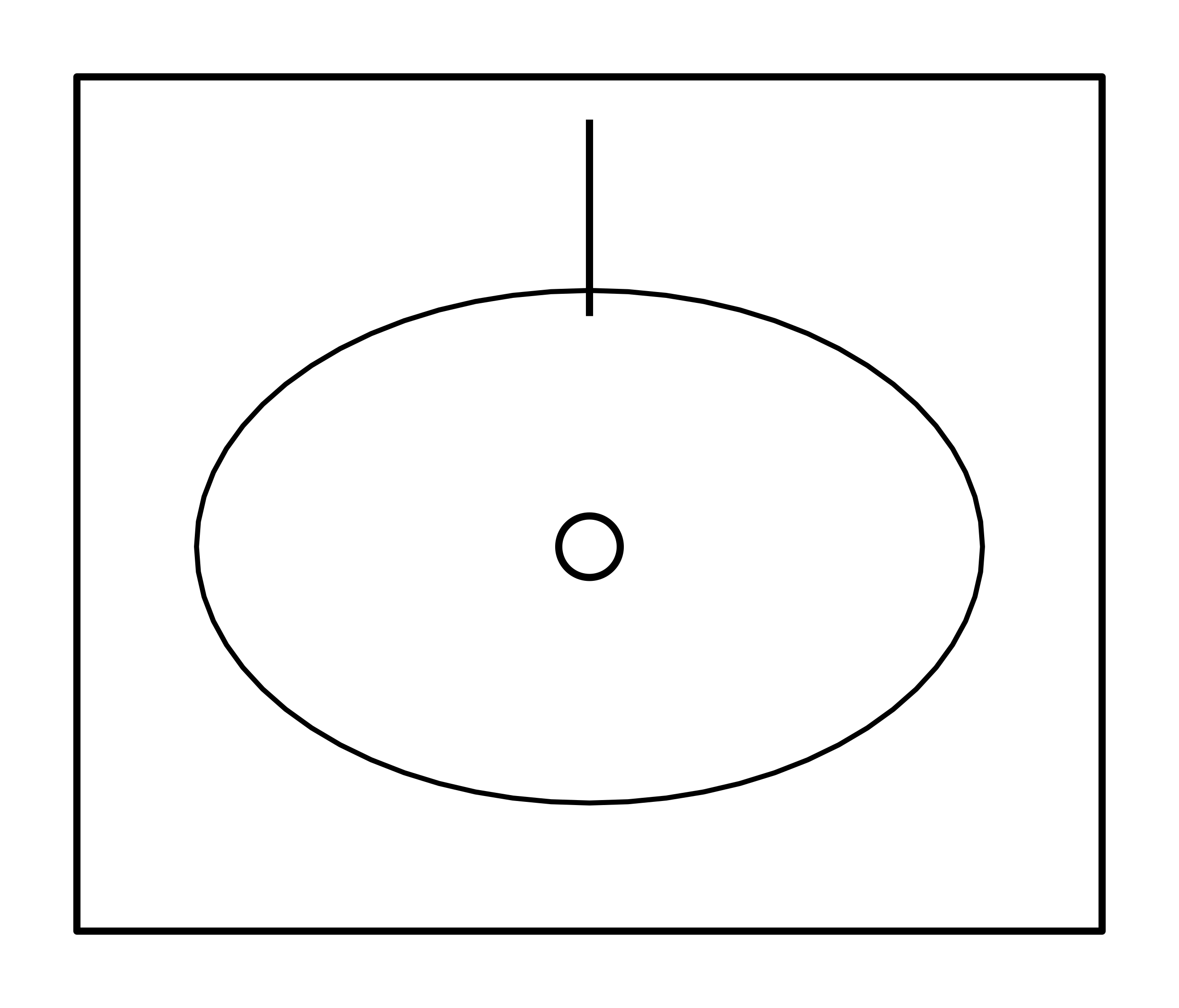
35 / BathroomBasin vanityTypical / 600 × 500 mm

True size model geometry
Typical size: 600 × 500 mm.
Overall drawn extents: 600 × 500 mm / 23.622 × 19.685 in.

Typical nominal dimensions; check your selected product and project clearances.

Sizes are not code requirements. DXF layer: A-FLOR-FIXT. Select import units explicitly and use insertion scale 1. SVG includes margin; PNG is fitted to a square transparent canvas.

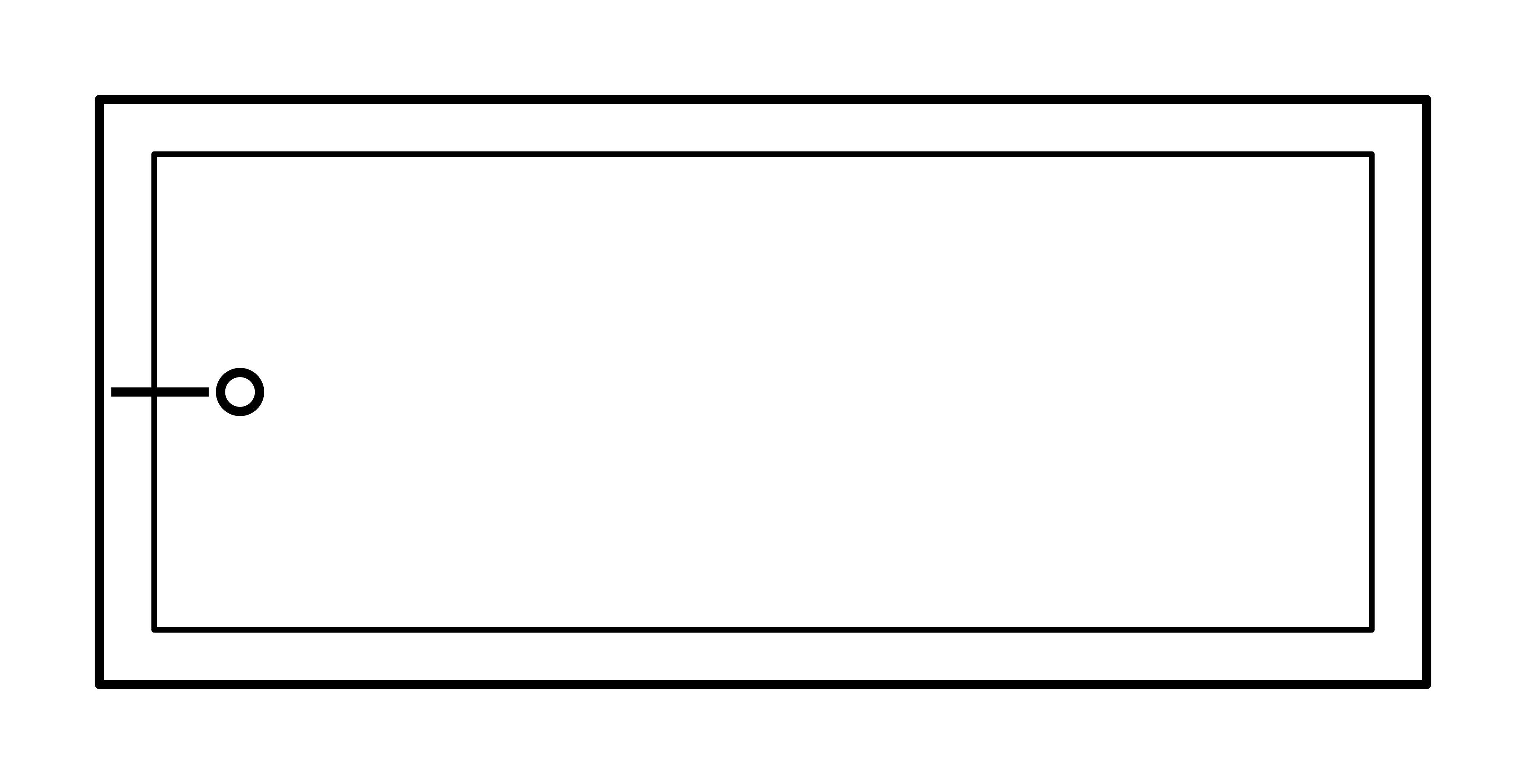
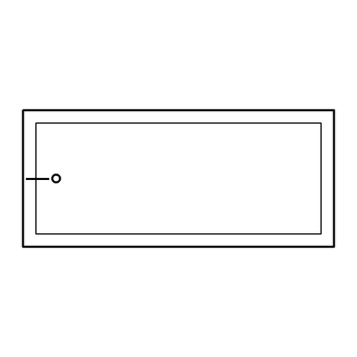
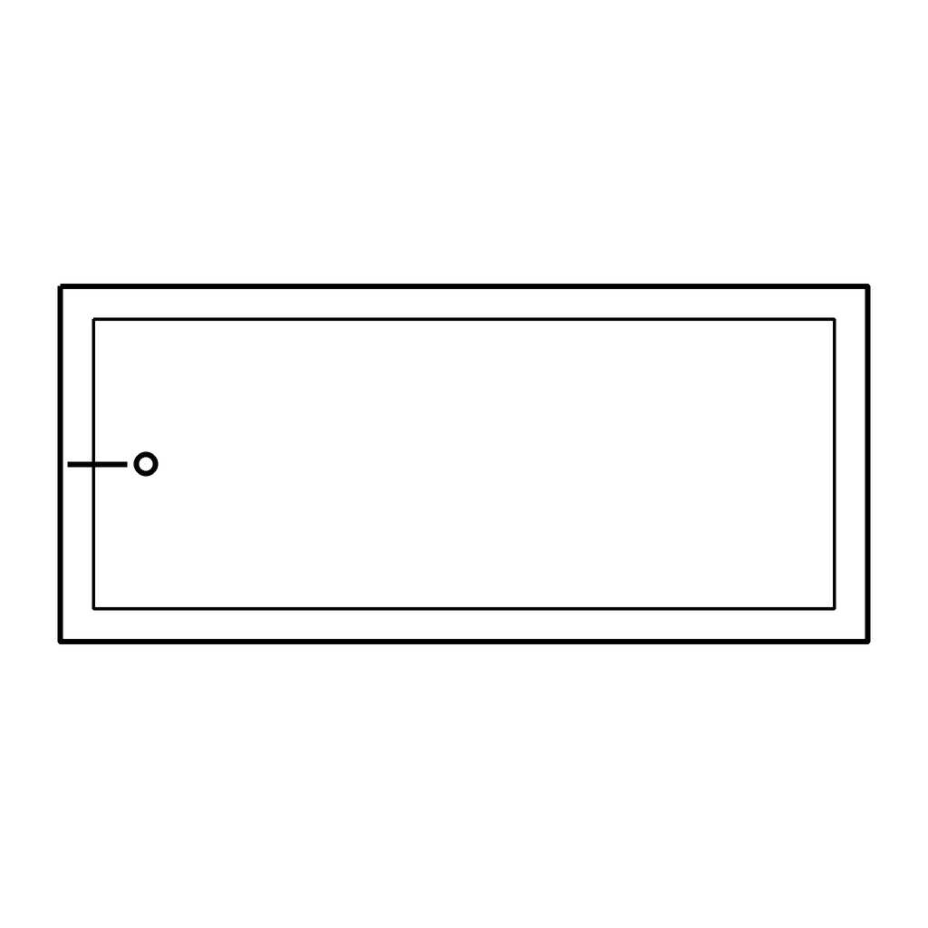
36 / BathroomBathtubTypical / 1700 × 750 mm

True size model geometry
Typical size: 1700 × 750 mm.
Overall drawn extents: 1700 × 750 mm / 66.929 × 29.528 in.

Typical nominal dimensions; check your selected product and project clearances.

Sizes are not code requirements. DXF layer: A-FLOR-FIXT. Select import units explicitly and use insertion scale 1. SVG includes margin; PNG is fitted to a square transparent canvas.

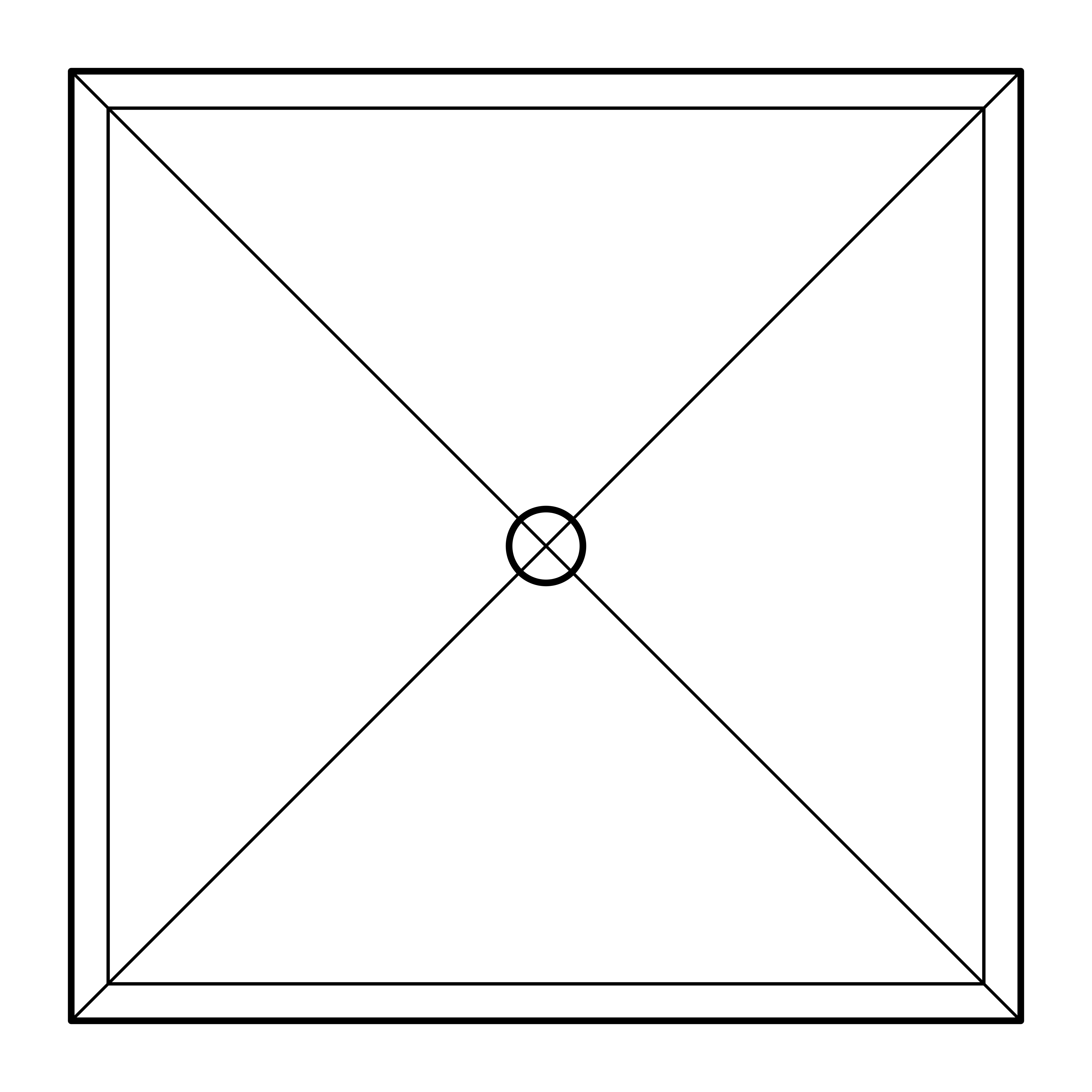
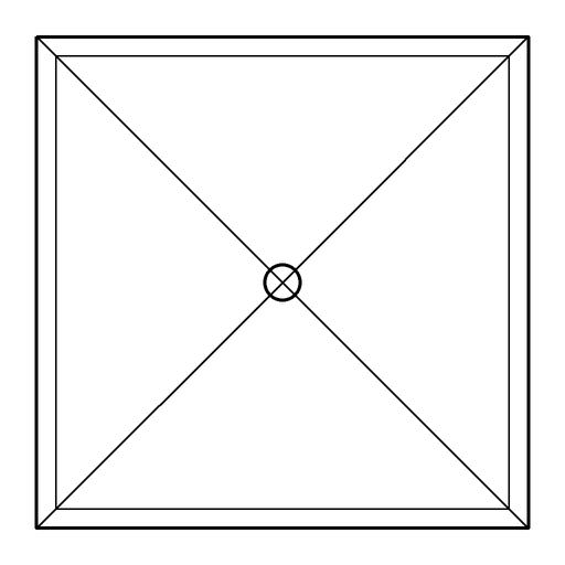
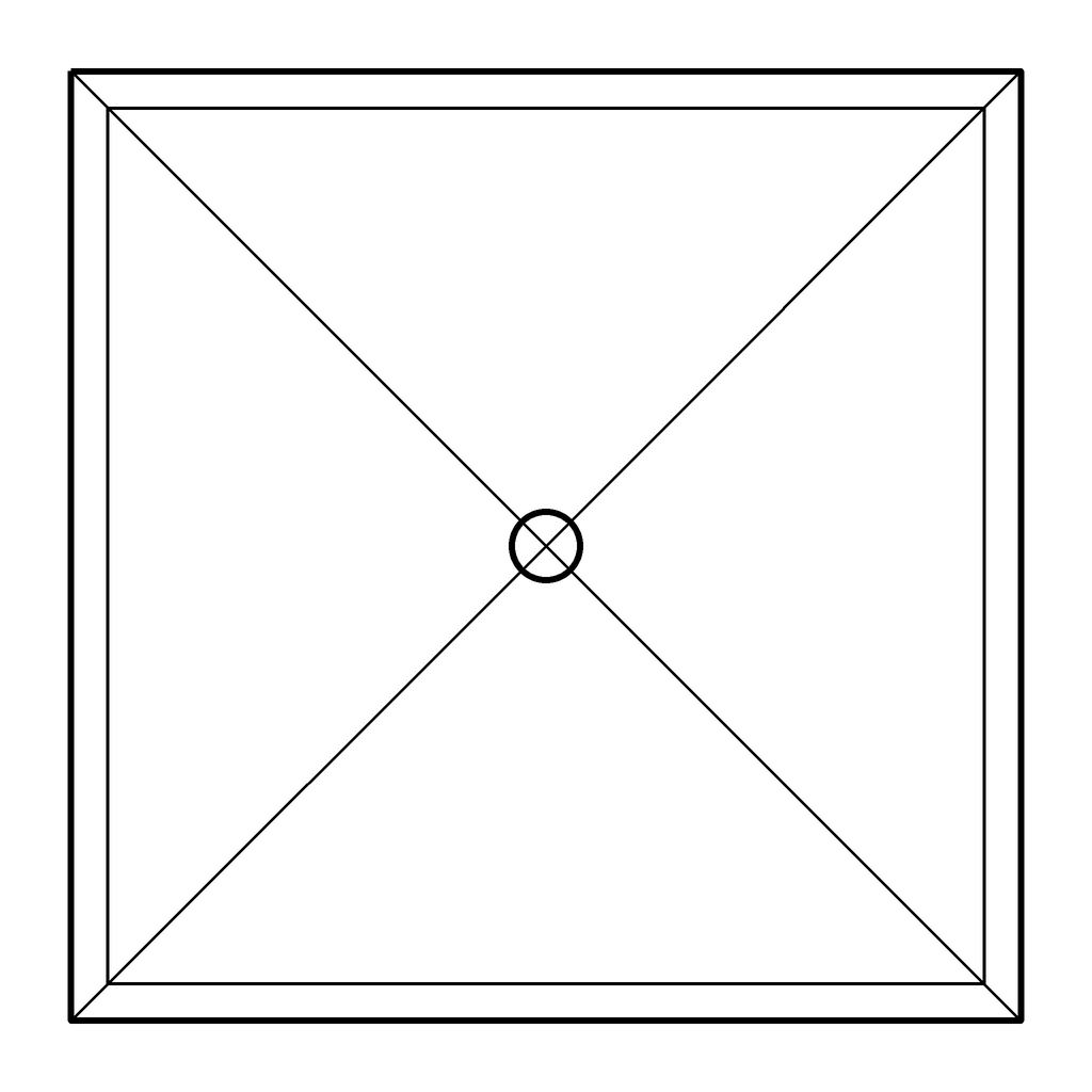
37 / BathroomSquare showerTypical / 900 × 900 mm

True size model geometry
Typical size: 900 × 900 mm.
Overall drawn extents: 900 × 900 mm / 35.433 × 35.433 in.

Typical nominal dimensions; check your selected product and project clearances.

Sizes are not code requirements. DXF layer: A-FLOR-FIXT. Select import units explicitly and use insertion scale 1. SVG includes margin; PNG is fitted to a square transparent canvas.

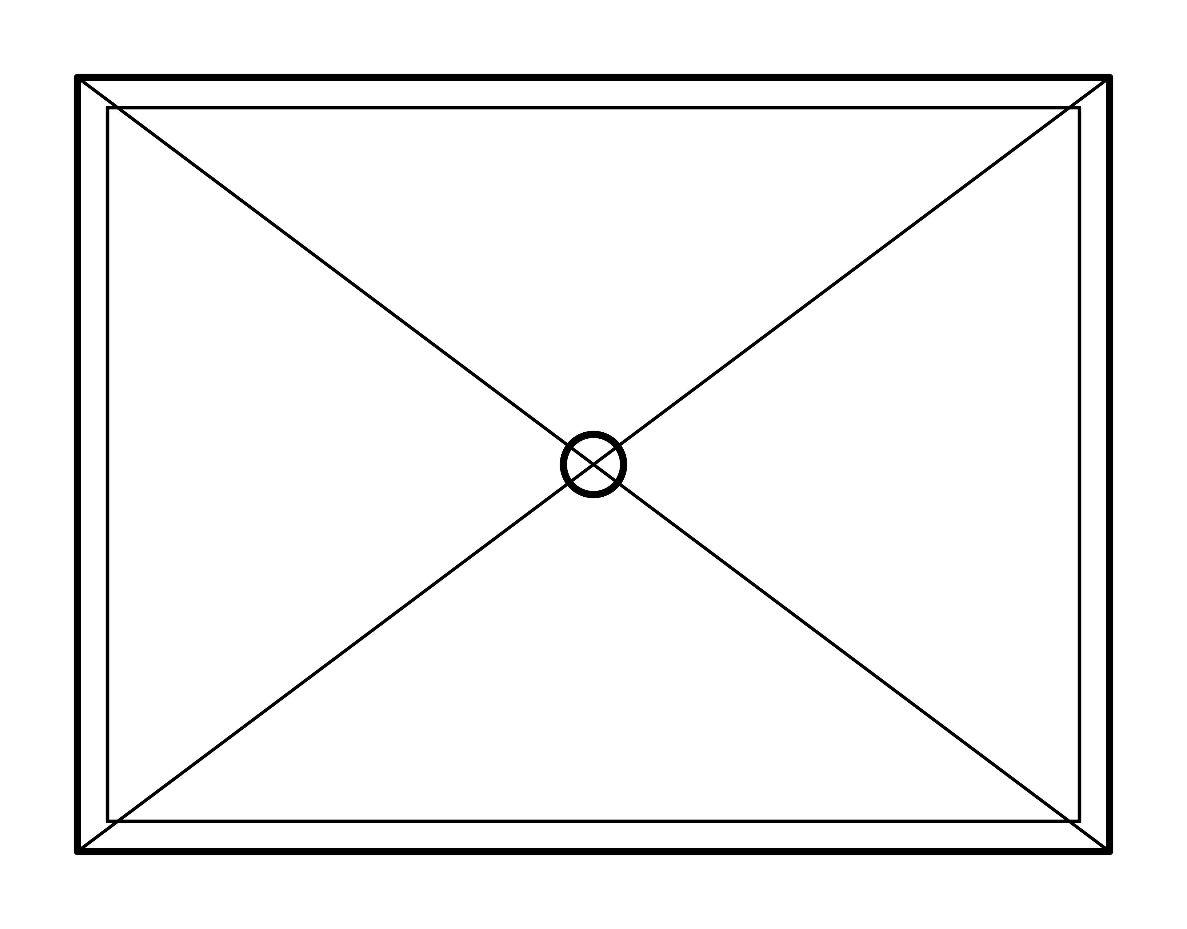
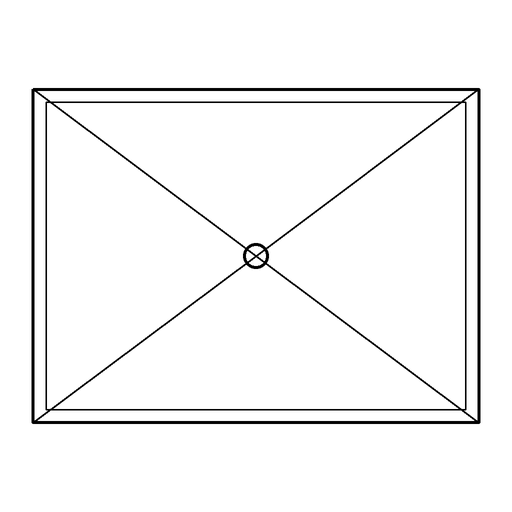
38 / BathroomRectangular showerTypical / 1200 × 900 mm

True size model geometry
Typical size: 1200 × 900 mm.
Overall drawn extents: 1200 × 900 mm / 47.244 × 35.433 in.

Typical nominal dimensions; check your selected product and project clearances.

Sizes are not code requirements. DXF layer: A-FLOR-FIXT. Select import units explicitly and use insertion scale 1. SVG includes margin; PNG is fitted to a square transparent canvas.

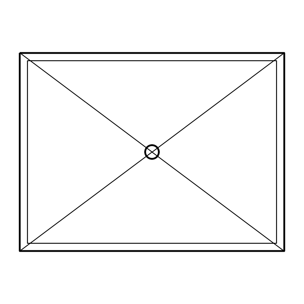
39 / BathroomFloor drainTypical / 150 × 150 mm

True size model geometry
Typical size: 150 × 150 mm.
Overall drawn extents: 150 × 150 mm / 5.906 × 5.906 in.

Typical nominal dimensions; check your selected product and project clearances.

Sizes are not code requirements. DXF layer: A-FLOR-FIXT. Select import units explicitly and use insertion scale 1. SVG includes margin; PNG is fitted to a square transparent canvas.

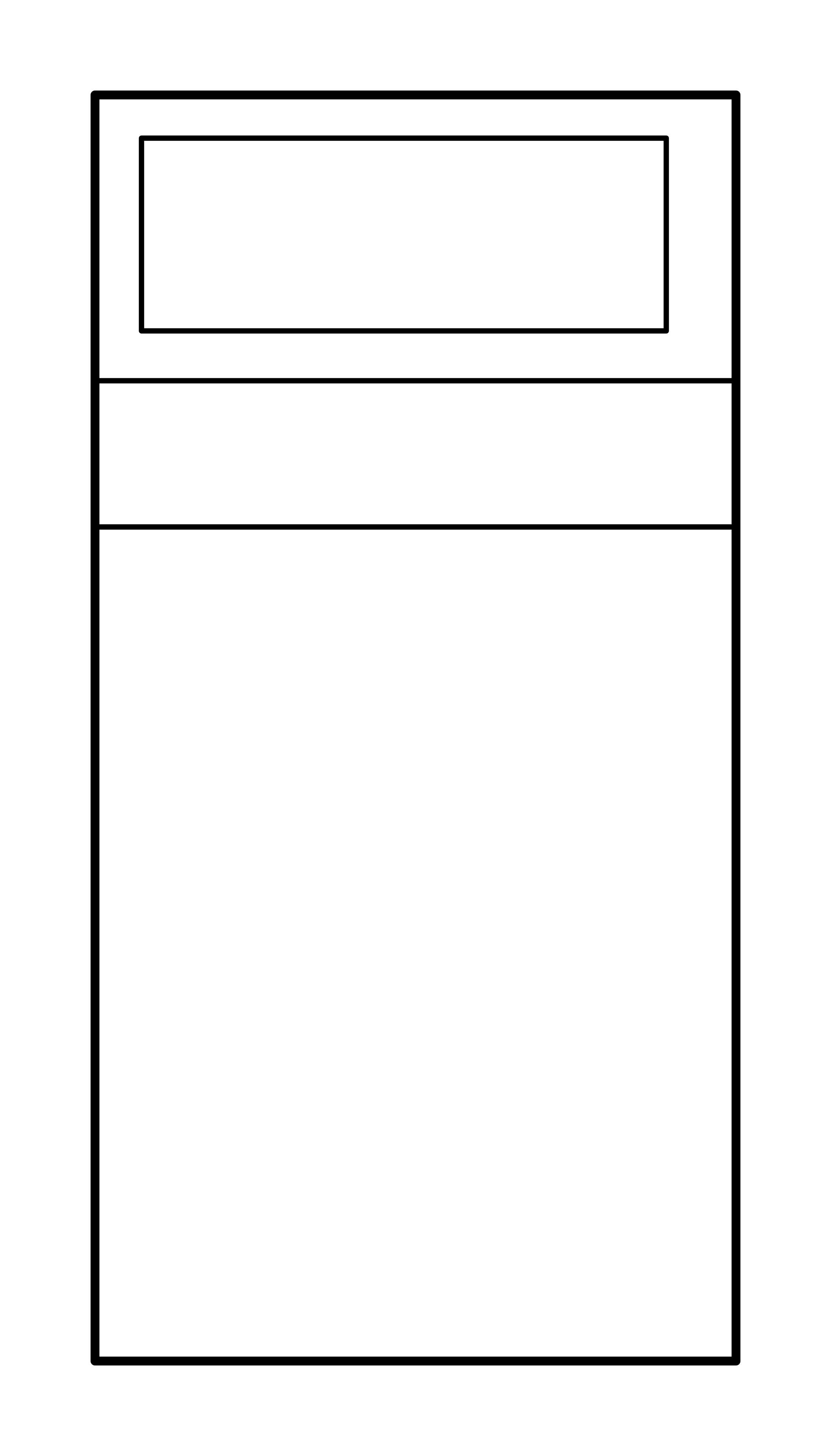
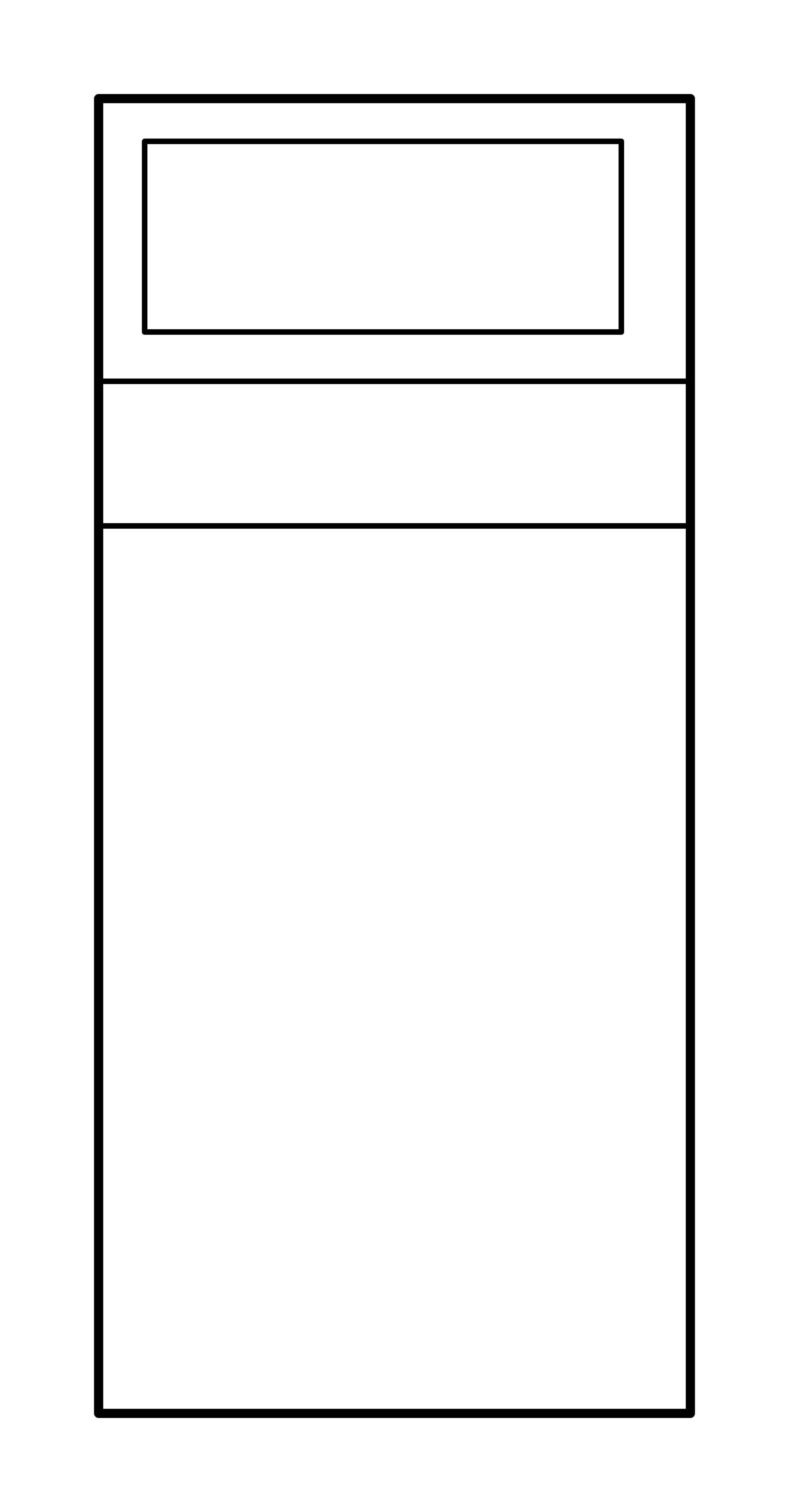
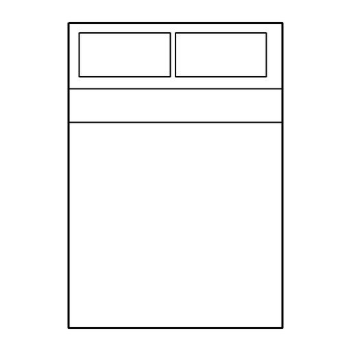
40 / FurnitureTwin bedTypical / 965 × 1905 mm

True size model geometry
Typical size: 965 × 1905 mm.
Overall drawn extents: 965 × 1905 mm / 37.992 × 75.000 in.

Typical mattress footprint; headboard, frame and circulation space are additional.

Sizes are not code requirements. DXF layer: A-FURN. Select import units explicitly and use insertion scale 1. SVG includes margin; PNG is fitted to a square transparent canvas.

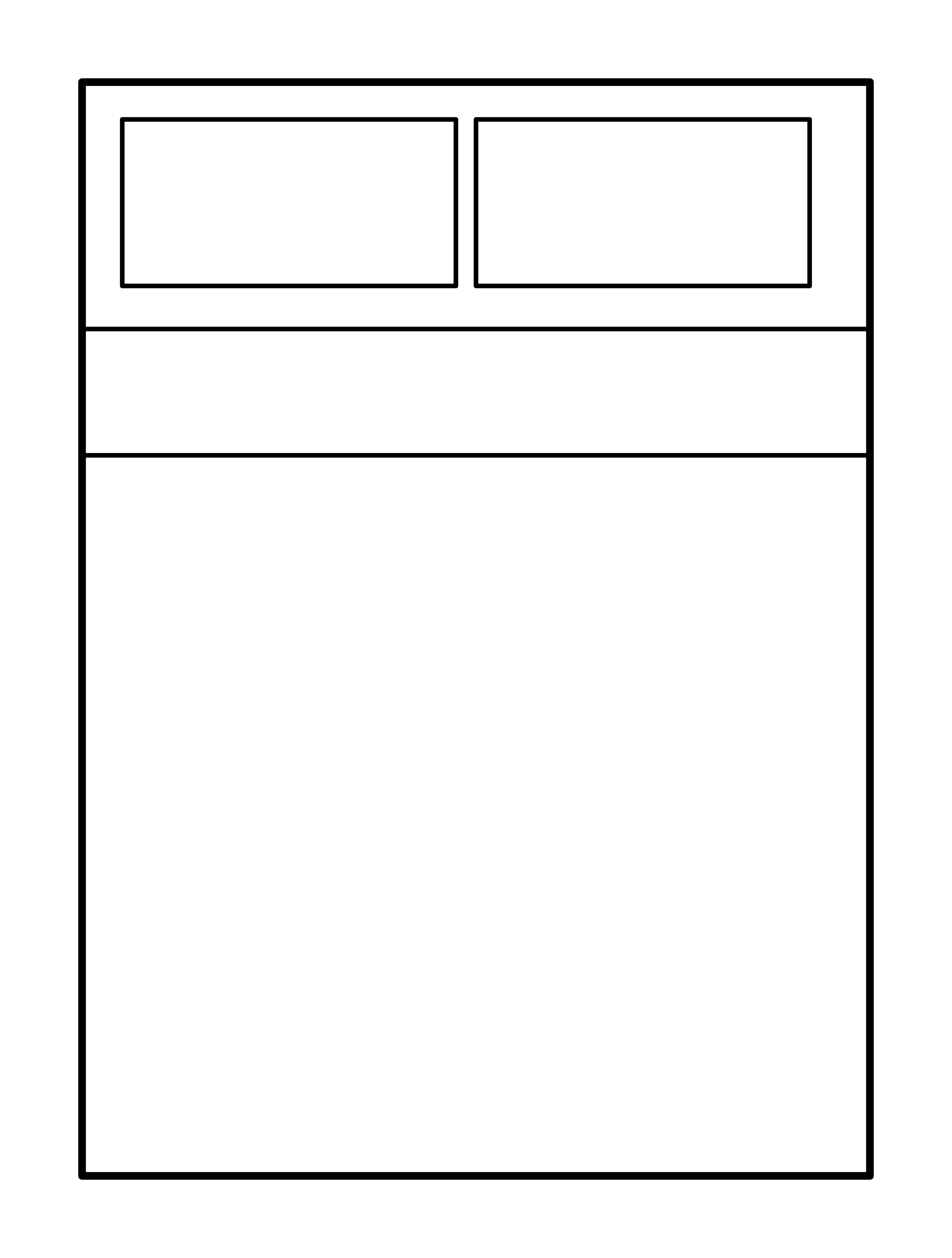
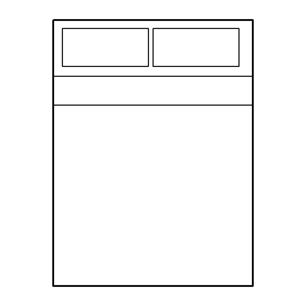
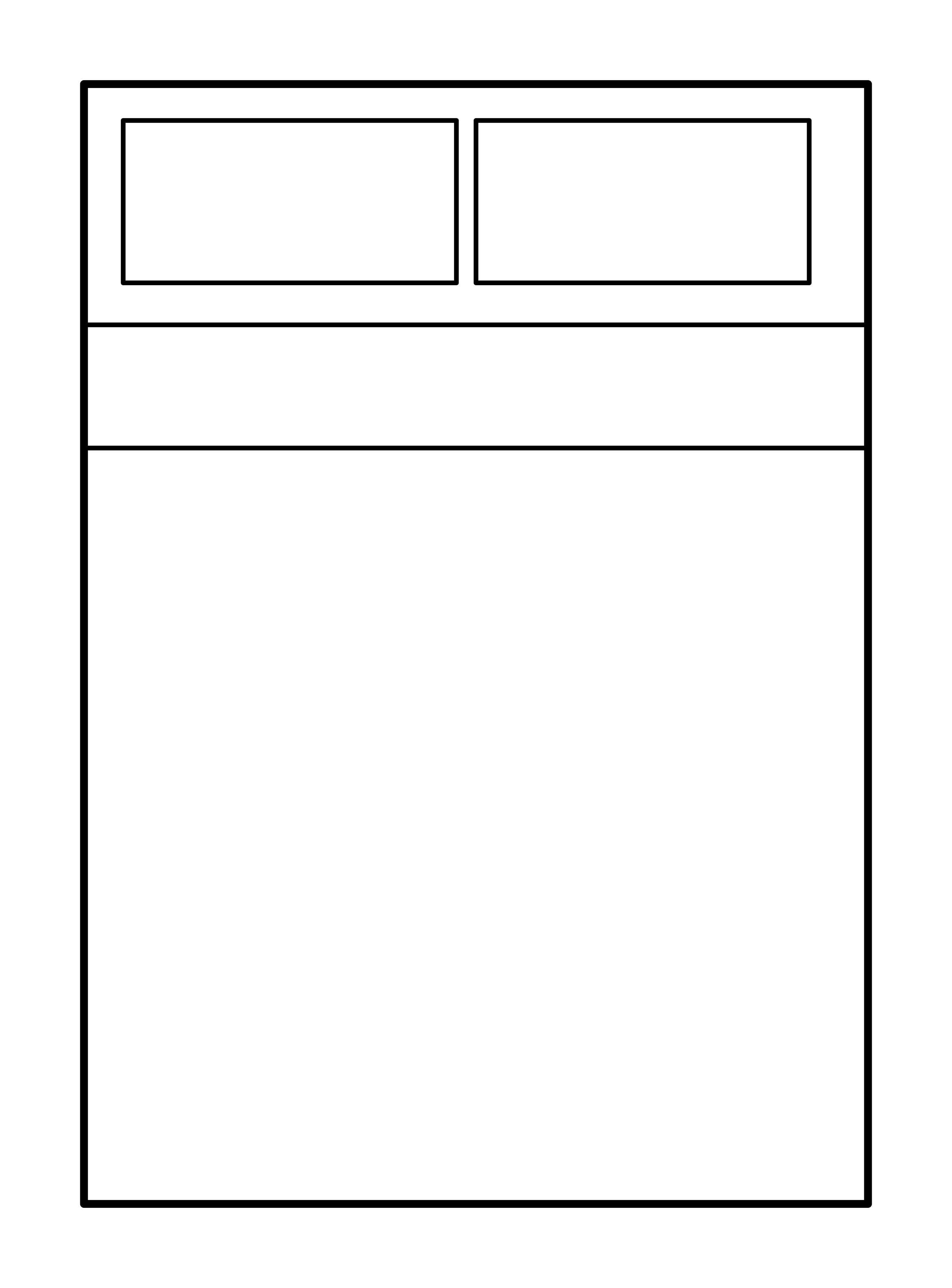
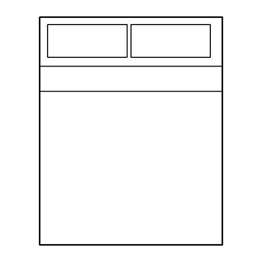
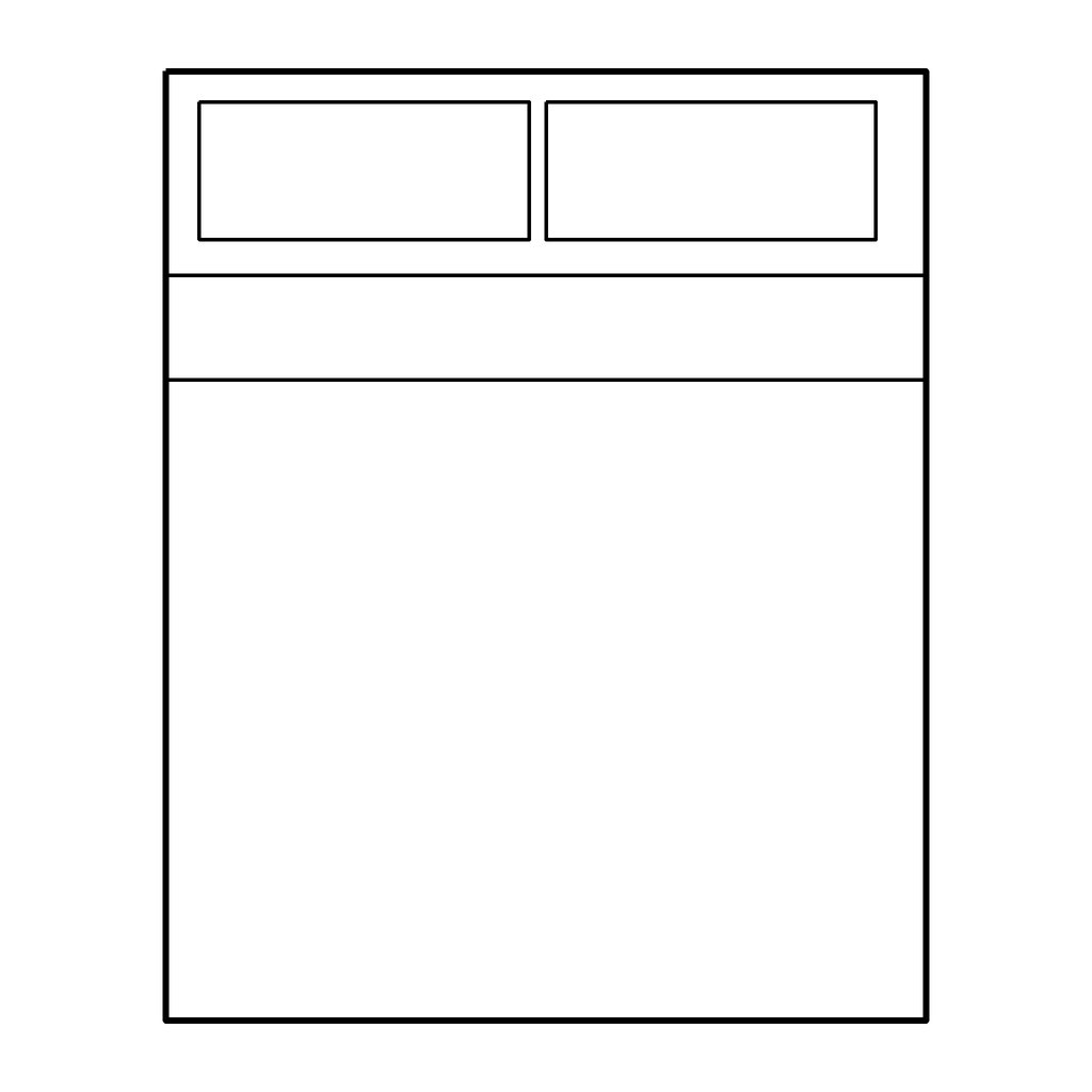
41 / FurnitureFull bedTypical / 1372 × 1905 mm

True size model geometry
Typical size: 1372 × 1905 mm.
Overall drawn extents: 1372 × 1905 mm / 54.016 × 75.000 in.

Typical mattress footprint; headboard, frame and circulation space are additional.

Sizes are not code requirements. DXF layer: A-FURN. Select import units explicitly and use insertion scale 1. SVG includes margin; PNG is fitted to a square transparent canvas.

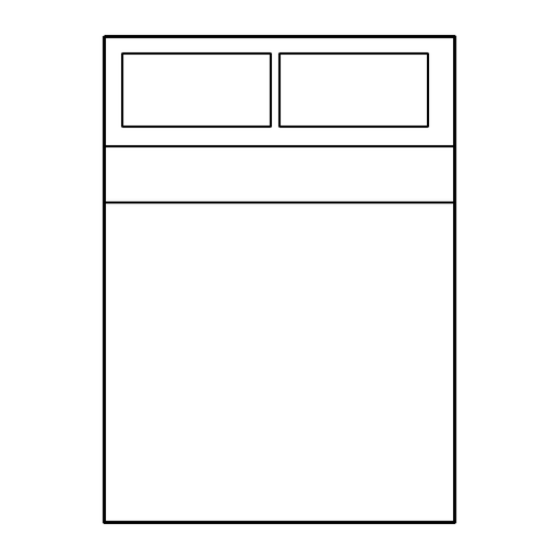
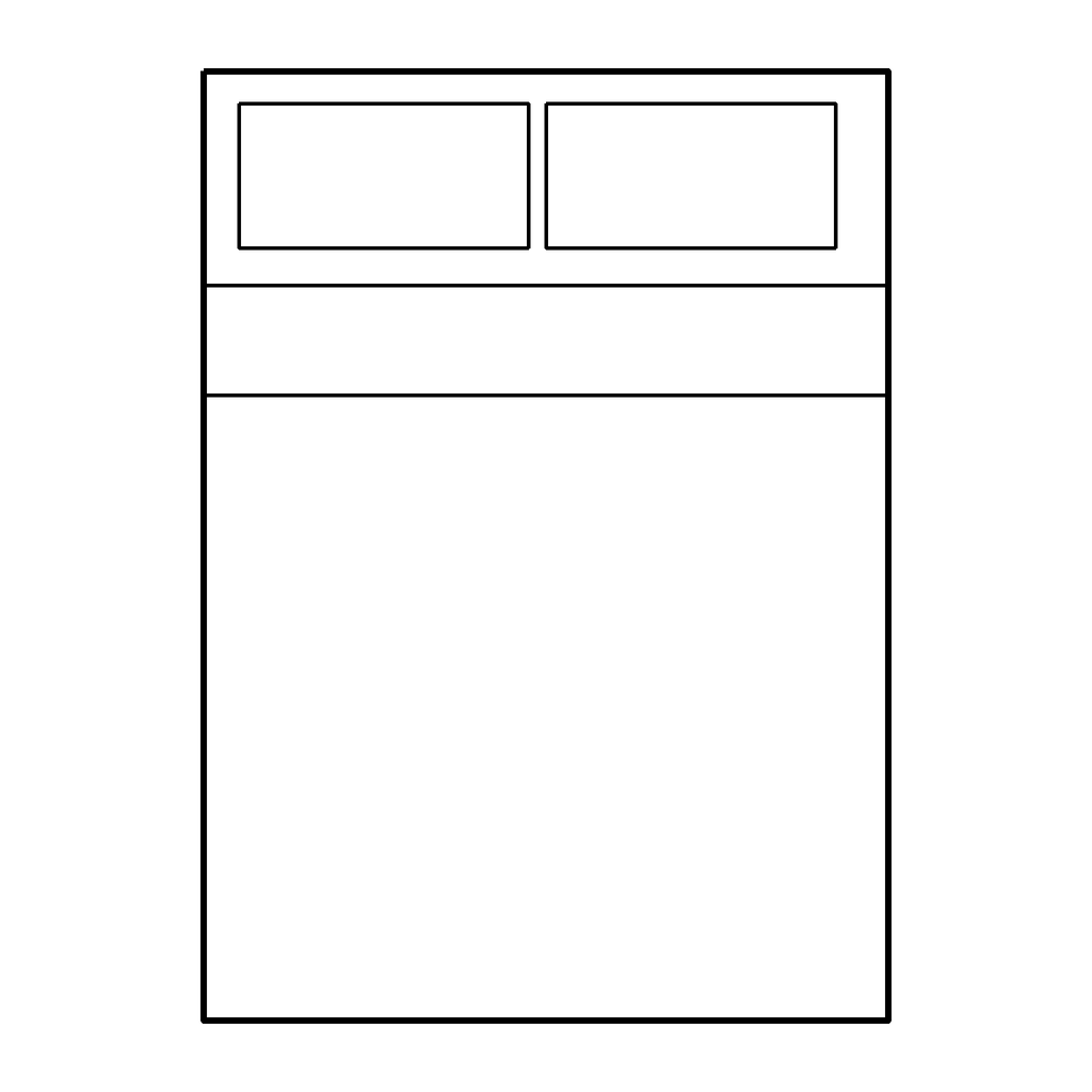
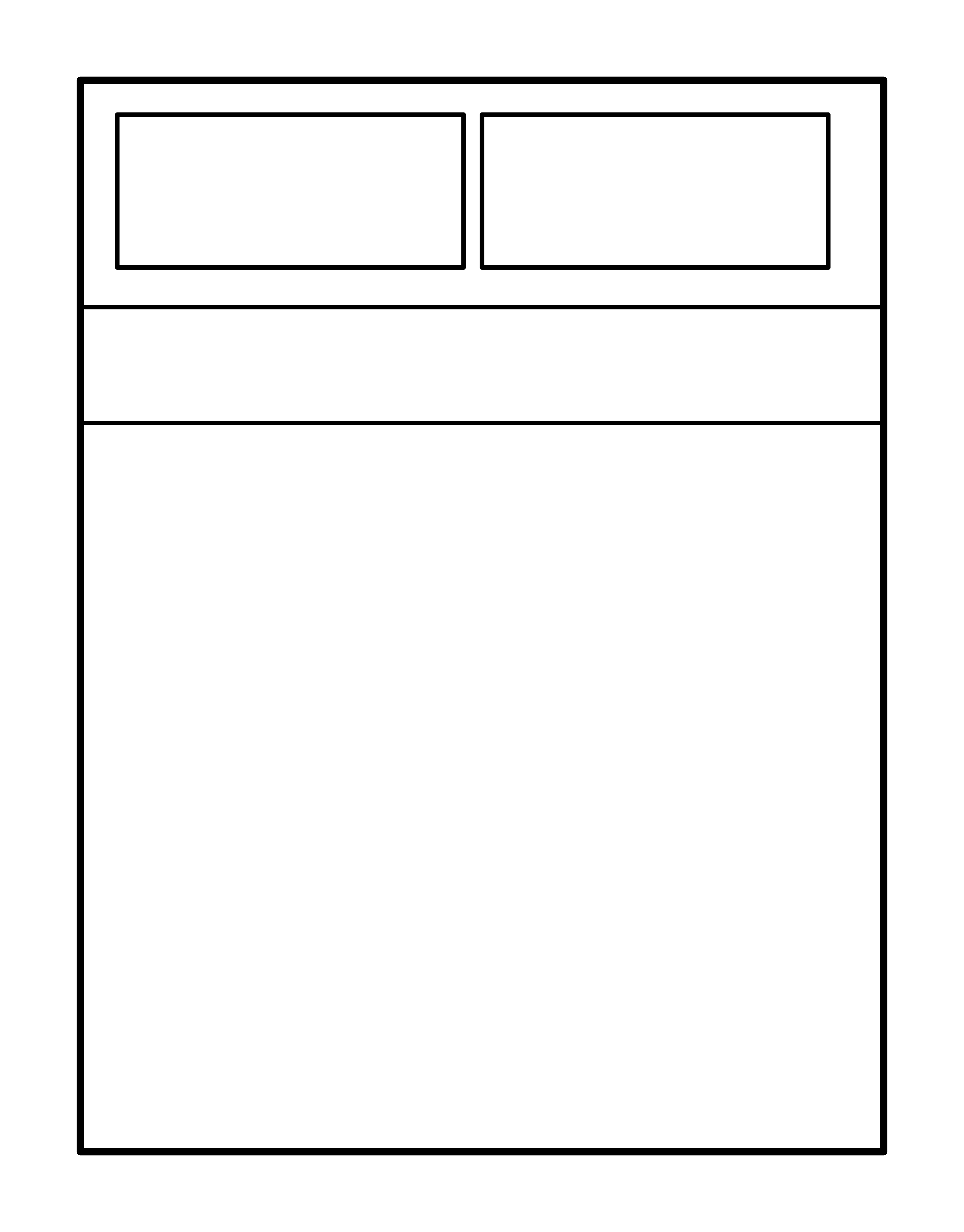
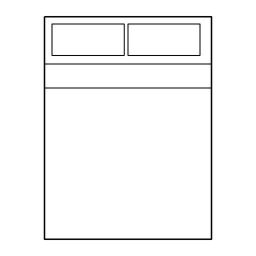
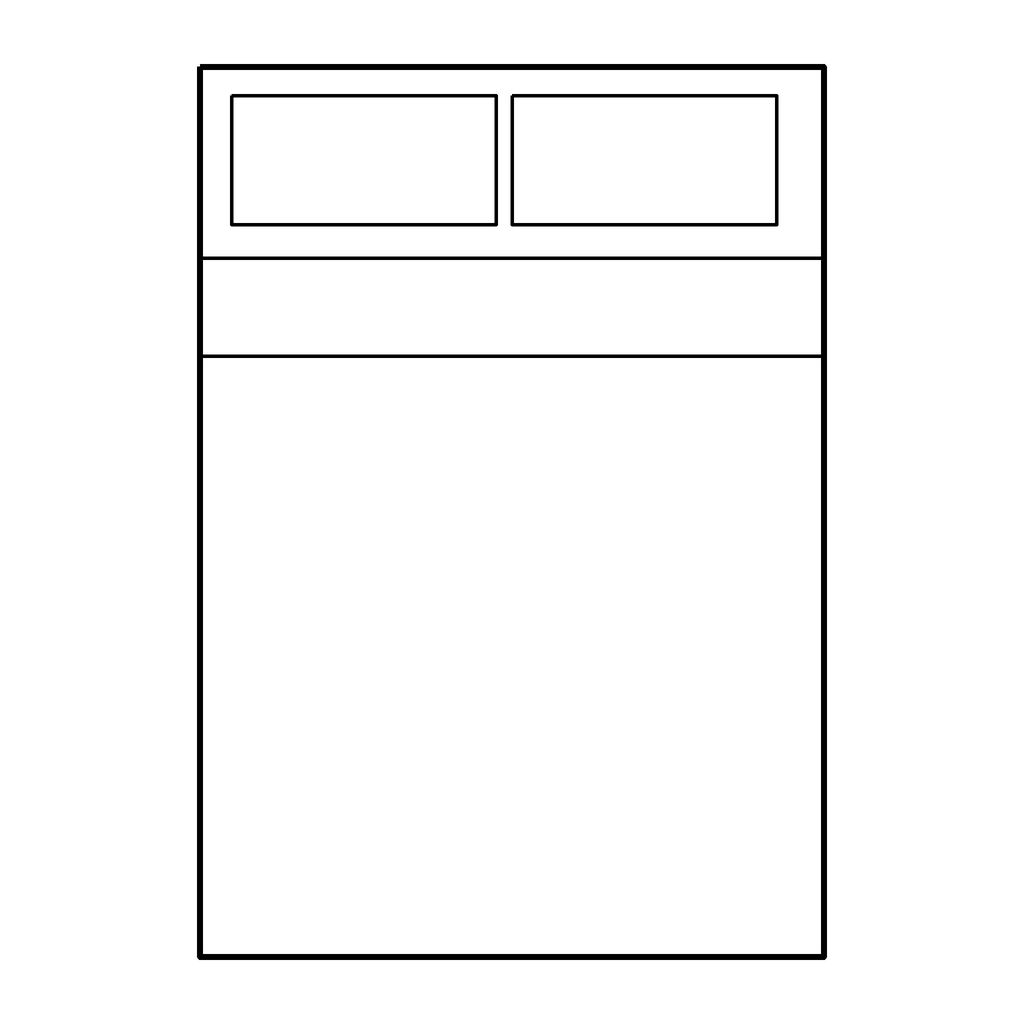
42 / FurnitureQueen bedTypical / 1524 × 2032 mm

True size model geometry
Typical size: 1524 × 2032 mm.
Overall drawn extents: 1524 × 2032 mm / 60.000 × 80.000 in.

Typical mattress footprint; headboard, frame and circulation space are additional.

Sizes are not code requirements. DXF layer: A-FURN. Select import units explicitly and use insertion scale 1. SVG includes margin; PNG is fitted to a square transparent canvas.

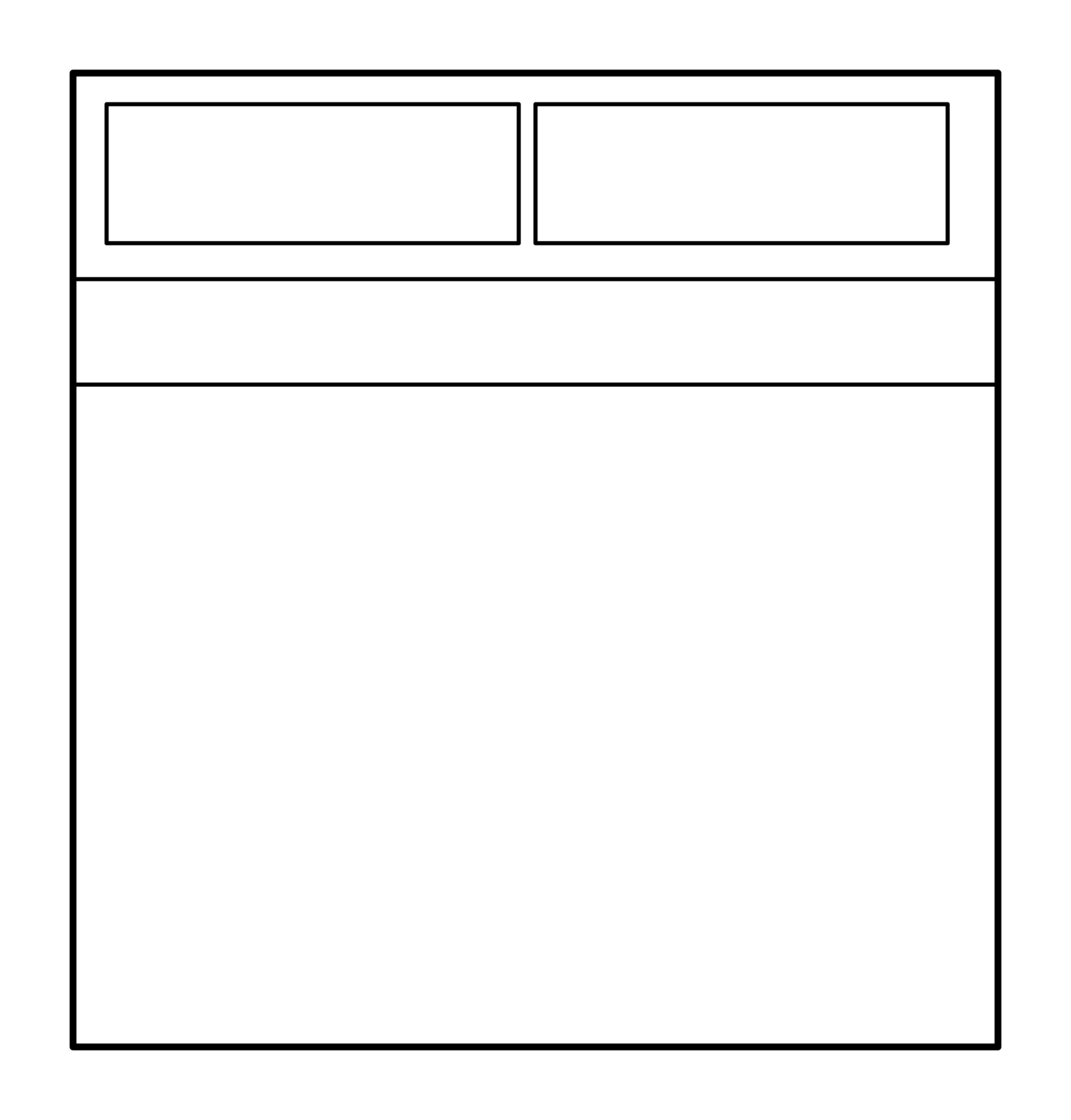
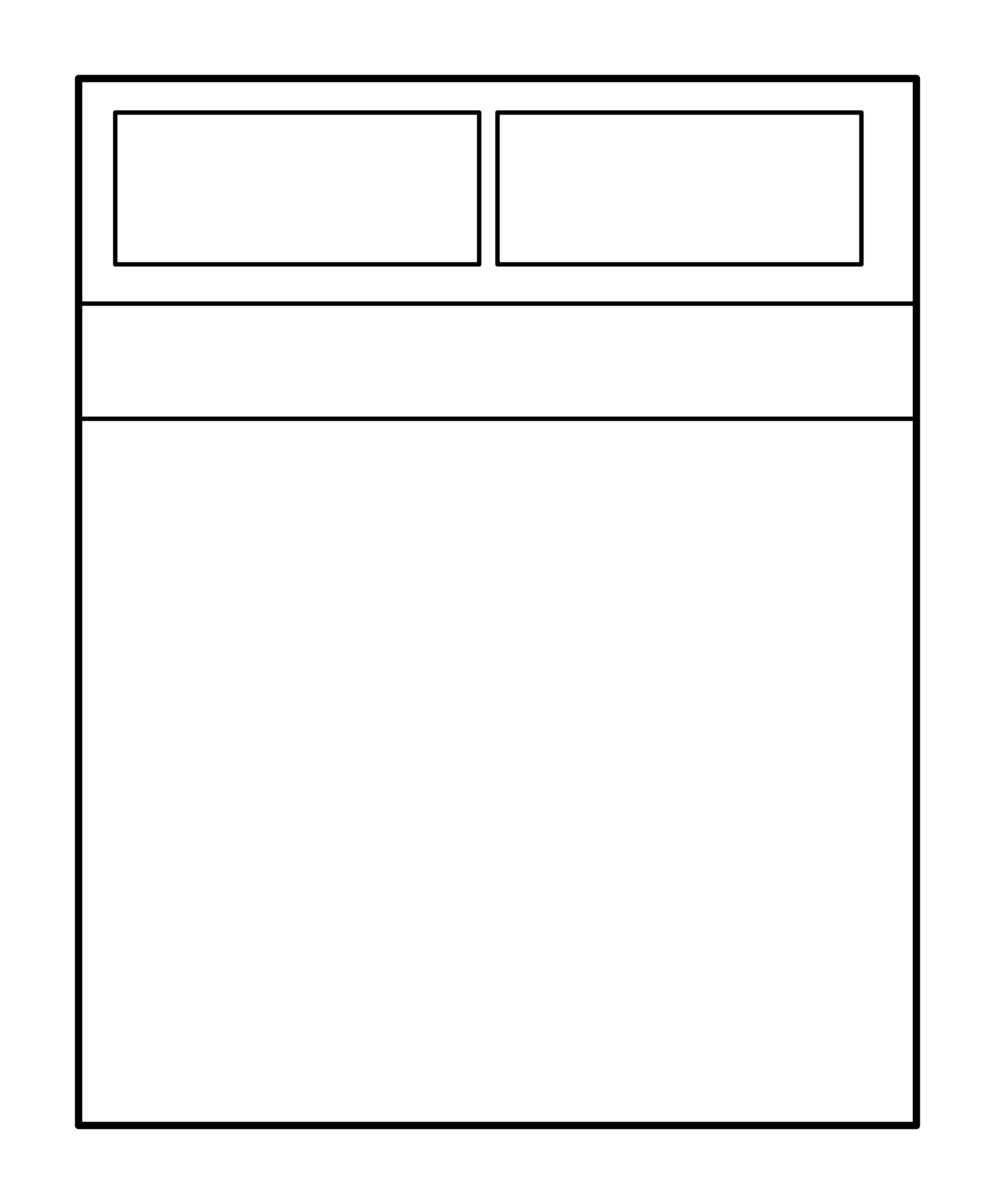
43 / FurnitureKing bedTypical / 1930 × 2032 mm

True size model geometry
Typical size: 1930 × 2032 mm.
Overall drawn extents: 1930 × 2032 mm / 75.984 × 80.000 in.

Typical mattress footprint; headboard, frame and circulation space are additional.

Sizes are not code requirements. DXF layer: A-FURN. Select import units explicitly and use insertion scale 1. SVG includes margin; PNG is fitted to a square transparent canvas.

44 / FurnitureBed 900Typical / 900 × 2000 mm

True size model geometry
Typical size: 900 × 2000 mm.
Overall drawn extents: 900 × 2000 mm / 35.433 × 78.740 in.

Typical mattress footprint; headboard, frame and circulation space are additional.

Sizes are not code requirements. DXF layer: A-FURN. Select import units explicitly and use insertion scale 1. SVG includes margin; PNG is fitted to a square transparent canvas.

45 / FurnitureBed 1400Typical / 1400 × 2000 mm

True size model geometry
Typical size: 1400 × 2000 mm.
Overall drawn extents: 1400 × 2000 mm / 55.118 × 78.740 in.

Typical mattress footprint; headboard, frame and circulation space are additional.

Sizes are not code requirements. DXF layer: A-FURN. Select import units explicitly and use insertion scale 1. SVG includes margin; PNG is fitted to a square transparent canvas.

46 / FurnitureBed 1600Typical / 1600 × 2000 mm

True size model geometry
Typical size: 1600 × 2000 mm.
Overall drawn extents: 1600 × 2000 mm / 62.992 × 78.740 in.

Typical mattress footprint; headboard, frame and circulation space are additional.

Sizes are not code requirements. DXF layer: A-FURN. Select import units explicitly and use insertion scale 1. SVG includes margin; PNG is fitted to a square transparent canvas.

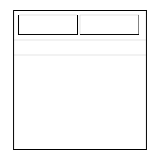
47 / FurnitureBed 1800Typical / 1800 × 2000 mm

True size model geometry
Typical size: 1800 × 2000 mm.
Overall drawn extents: 1800 × 2000 mm / 70.866 × 78.740 in.

Typical mattress footprint; headboard, frame and circulation space are additional.

Sizes are not code requirements. DXF layer: A-FURN. Select import units explicitly and use insertion scale 1. SVG includes margin; PNG is fitted to a square transparent canvas.

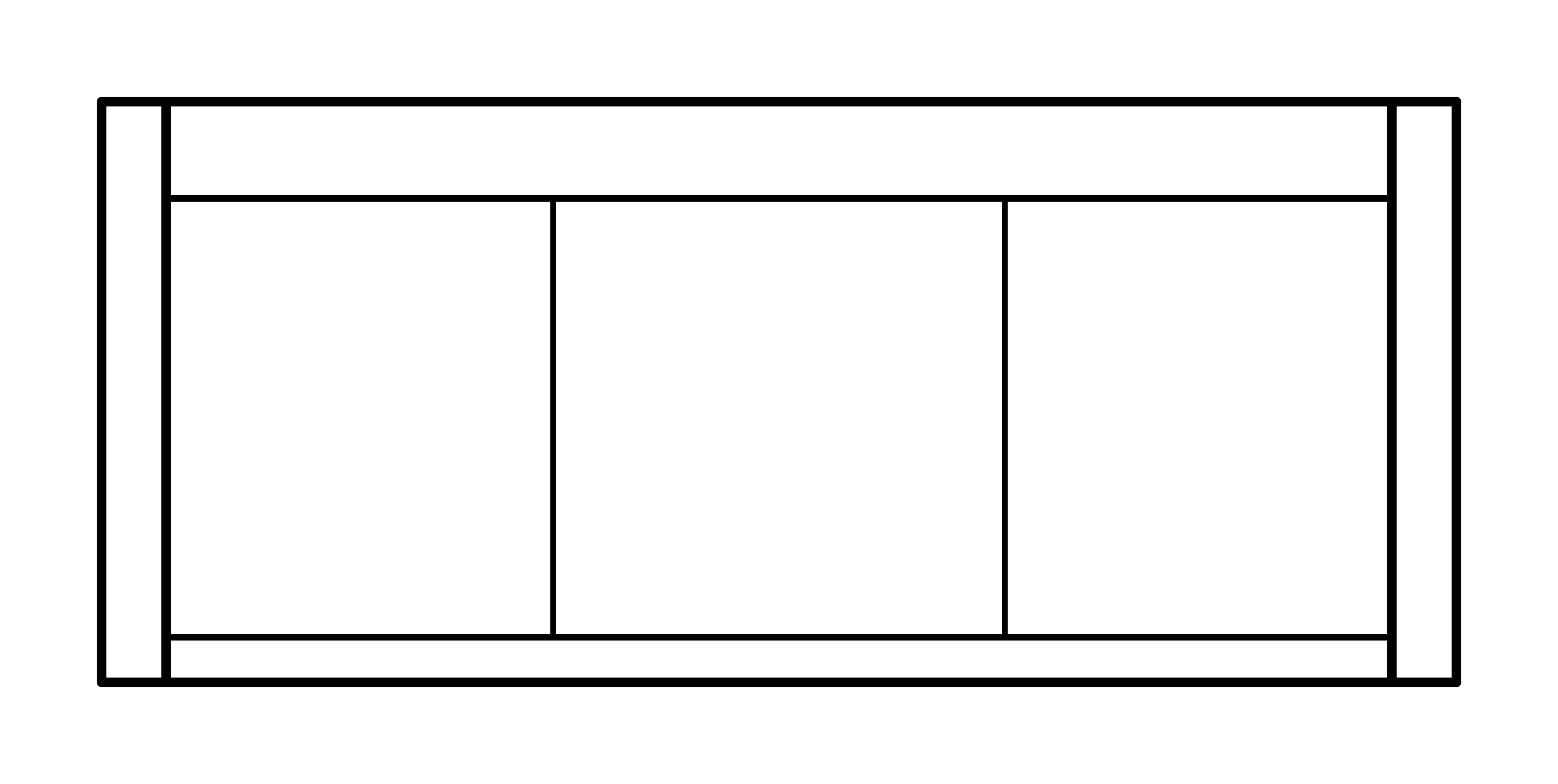
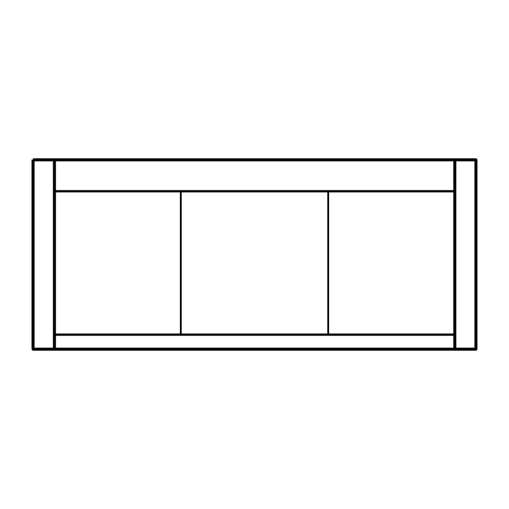
48 / FurnitureSofaTypical / 2100 × 900 mm

True size model geometry
Typical size: 2100 × 900 mm.
Overall drawn extents: 2100 × 900 mm / 82.677 × 35.433 in.

Typical overall geometry. Tables include chair footprints; desk includes its chair.

Sizes are not code requirements. DXF layer: A-FURN. Select import units explicitly and use insertion scale 1. SVG includes margin; PNG is fitted to a square transparent canvas.

49 / FurnitureArmchairTypical / 850 × 850 mm

True size model geometry
Typical size: 850 × 850 mm.
Overall drawn extents: 850 × 850 mm / 33.465 × 33.465 in.

Typical overall geometry. Tables include chair footprints; desk includes its chair.

Sizes are not code requirements. DXF layer: A-FURN. Select import units explicitly and use insertion scale 1. SVG includes margin; PNG is fitted to a square transparent canvas.

50 / FurnitureDining table 4Typical / 1800 × 1600 mm

True size model geometry
Typical size: 1800 × 1600 mm.
Overall drawn extents: 1800 × 1600 mm / 70.866 × 62.992 in.

Typical overall geometry. Tables include chair footprints; desk includes its chair.

Sizes are not code requirements. DXF layer: A-FURN. Select import units explicitly and use insertion scale 1. SVG includes margin; PNG is fitted to a square transparent canvas.

51 / FurnitureDining table 6Typical / 2400 × 1800 mm

True size model geometry
Typical size: 2400 × 1800 mm.
Overall drawn extents: 2400 × 1800 mm / 94.488 × 70.866 in.

Typical overall geometry. Tables include chair footprints; desk includes its chair.

Sizes are not code requirements. DXF layer: A-FURN. Select import units explicitly and use insertion scale 1. SVG includes margin; PNG is fitted to a square transparent canvas.

52 / FurnitureDesk and chairTypical / 1400 × 1400 mm

True size model geometry
Typical size: 1400 × 1400 mm.
Overall drawn extents: 1400 × 1400 mm / 55.118 × 55.118 in.

Typical overall geometry. Tables include chair footprints; desk includes its chair.

Sizes are not code requirements. DXF layer: A-FURN. Select import units explicitly and use insertion scale 1. SVG includes margin; PNG is fitted to a square transparent canvas.

53 / FurnitureWardrobeTypical / 1800 × 600 mm

True size model geometry
Typical size: 1800 × 600 mm.
Overall drawn extents: 1800 × 600 mm / 70.866 × 23.622 in.

Typical overall geometry. Tables include chair footprints; desk includes its chair.

Sizes are not code requirements. DXF layer: A-FURN. Select import units explicitly and use insertion scale 1. SVG includes margin; PNG is fitted to a square transparent canvas.

54 / Electrical and lightingDuplex outletTypical / 6 × 6 mm paper graphic at 1:1

Paper graphic at 1:1
Typical size: 6 × 6 mm paper graphic at 1:1.
Overall drawn extents: 6 × 6 mm / 0.236 × 0.236 in.

Paper graphic, not an equipment footprint. Define its meaning in your project legend.

Sizes are not code requirements. DXF layer: E-POWR. Select import units explicitly and use insertion scale 1. SVG includes margin; PNG is fitted to a square transparent canvas.

55 / Electrical and lightingGFCI outletTypical / 8.78 × 6 mm paper graphic at 1:1

Paper graphic at 1:1
Typical size: 8.78 × 6 mm paper graphic at 1:1.
Overall drawn extents: 8.78 × 6 mm / 0.346 × 0.236 in.

Paper graphic, not an equipment footprint. Define its meaning in your project legend.

Sizes are not code requirements. DXF layer: E-POWR. Select import units explicitly and use insertion scale 1. SVG includes margin; PNG is fitted to a square transparent canvas.

56 / Electrical and lightingSwitchTypical / 3.6 × 6 mm paper graphic at 1:1

Paper graphic at 1:1
Typical size: 3.6 × 6 mm paper graphic at 1:1.
Overall drawn extents: 3.6 × 6 mm / 0.142 × 0.236 in.

Paper graphic, not an equipment footprint. Define its meaning in your project legend.

Sizes are not code requirements. DXF layer: E-POWR. Select import units explicitly and use insertion scale 1. SVG includes margin; PNG is fitted to a square transparent canvas.

57 / Electrical and lighting3 way switchTypical / 7.2 × 6 mm paper graphic at 1:1

Paper graphic at 1:1
Typical size: 7.2 × 6 mm paper graphic at 1:1.
Overall drawn extents: 7.2 × 6 mm / 0.283 × 0.236 in.

Paper graphic, not an equipment footprint. Define its meaning in your project legend.

Sizes are not code requirements. DXF layer: E-POWR. Select import units explicitly and use insertion scale 1. SVG includes margin; PNG is fitted to a square transparent canvas.

58 / Electrical and lightingCeiling lightTypical / 10 × 10 mm paper graphic at 1:1

Paper graphic at 1:1
Typical size: 10 × 10 mm paper graphic at 1:1.
Overall drawn extents: 10 × 10 mm / 0.394 × 0.394 in.

Paper graphic, not an equipment footprint. Define its meaning in your project legend.

Sizes are not code requirements. DXF layer: E-LITE. Select import units explicitly and use insertion scale 1. SVG includes margin; PNG is fitted to a square transparent canvas.

59 / Electrical and lightingRecessed downlightTypical / 6 × 6 mm paper graphic at 1:1

Paper graphic at 1:1
Typical size: 6 × 6 mm paper graphic at 1:1.
Overall drawn extents: 6 × 6 mm / 0.236 × 0.236 in.

Paper graphic, not an equipment footprint. Define its meaning in your project legend.

Sizes are not code requirements. DXF layer: E-LITE. Select import units explicitly and use insertion scale 1. SVG includes margin; PNG is fitted to a square transparent canvas.

60 / Electrical and lightingWall lightTypical / 10 × 5 mm paper graphic at 1:1

Paper graphic at 1:1
Typical size: 10 × 5 mm paper graphic at 1:1.
Overall drawn extents: 10 × 5 mm / 0.394 × 0.197 in.

Paper graphic, not an equipment footprint. Define its meaning in your project legend.

Sizes are not code requirements. DXF layer: E-LITE. Select import units explicitly and use insertion scale 1. SVG includes margin; PNG is fitted to a square transparent canvas.

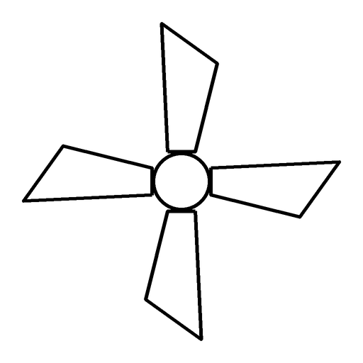
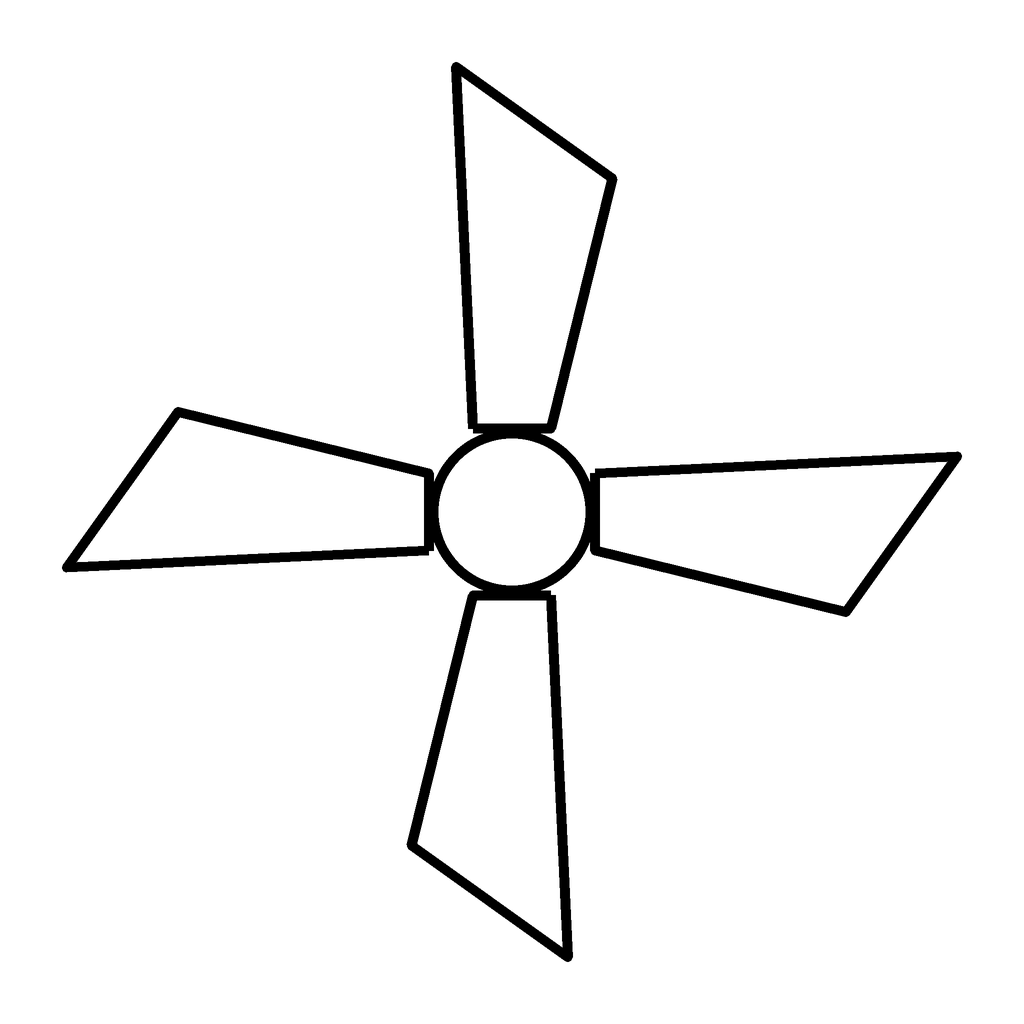
61 / Electrical and lightingCeiling fanTypical / 16 × 16 mm paper graphic at 1:1

Paper graphic at 1:1
Typical size: 16 × 16 mm paper graphic at 1:1.
Overall drawn extents: 16 × 16 mm / 0.630 × 0.630 in.

Paper graphic, not an equipment footprint. Define its meaning in your project legend.

Sizes are not code requirements. DXF layer: E-LITE. Select import units explicitly and use insertion scale 1. SVG includes margin; PNG is fitted to a square transparent canvas.

62 / Electrical and lightingData outletTypical / 8 × 8 mm paper graphic at 1:1

Paper graphic at 1:1
Typical size: 8 × 8 mm paper graphic at 1:1.
Overall drawn extents: 8 × 8 mm / 0.315 × 0.315 in.

Paper graphic, not an equipment footprint. Define its meaning in your project legend.

Sizes are not code requirements. DXF layer: E-POWR. Select import units explicitly and use insertion scale 1. SVG includes margin; PNG is fitted to a square transparent canvas.

63 / Electrical and lightingSmoke detectorTypical / 10 × 10 mm paper graphic at 1:1

Paper graphic at 1:1
Typical size: 10 × 10 mm paper graphic at 1:1.
Overall drawn extents: 10 × 10 mm / 0.394 × 0.394 in.

Paper graphic, not an equipment footprint. Define its meaning in your project legend.

Sizes are not code requirements. DXF layer: E-POWR. Select import units explicitly and use insertion scale 1. SVG includes margin; PNG is fitted to a square transparent canvas.

64 / Electrical and lightingSwitch legTypical / 38.4 × 16 mm paper graphic at 1:1

Paper graphic at 1:1
Typical size: 38.4 × 16 mm paper graphic at 1:1.
Overall drawn extents: 38.4 × 16 mm / 1.512 × 0.630 in.

Paper graphic, not an equipment footprint. Define its meaning in your project legend.

Sizes are not code requirements. DXF layer: E-LITE. Select import units explicitly and use insertion scale 1. SVG includes margin; PNG is fitted to a square transparent canvas.

65 / AnnotationSection cut markerTypical / 32 × 10 mm paper graphic at 1:1

Paper graphic at 1:1
Typical size: 32 × 10 mm paper graphic at 1:1.
Overall drawn extents: 32 × 10 mm / 1.260 × 0.394 in.

Paper size at 1:1. Scale for model space or place in a sheet view.

Sizes are not code requirements. DXF layer: A-ANNO. Select import units explicitly and use insertion scale 1. SVG includes margin; PNG is fitted to a square transparent canvas.

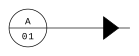
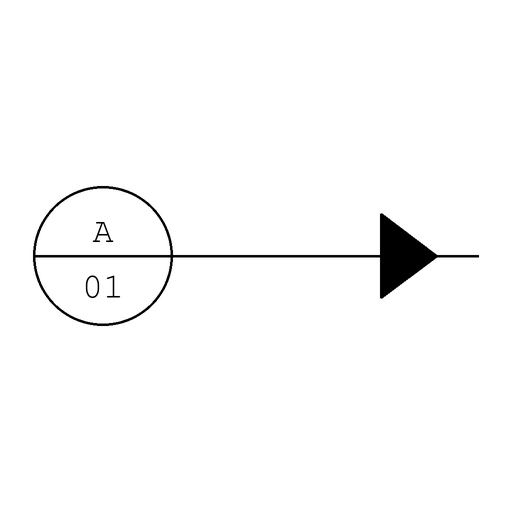
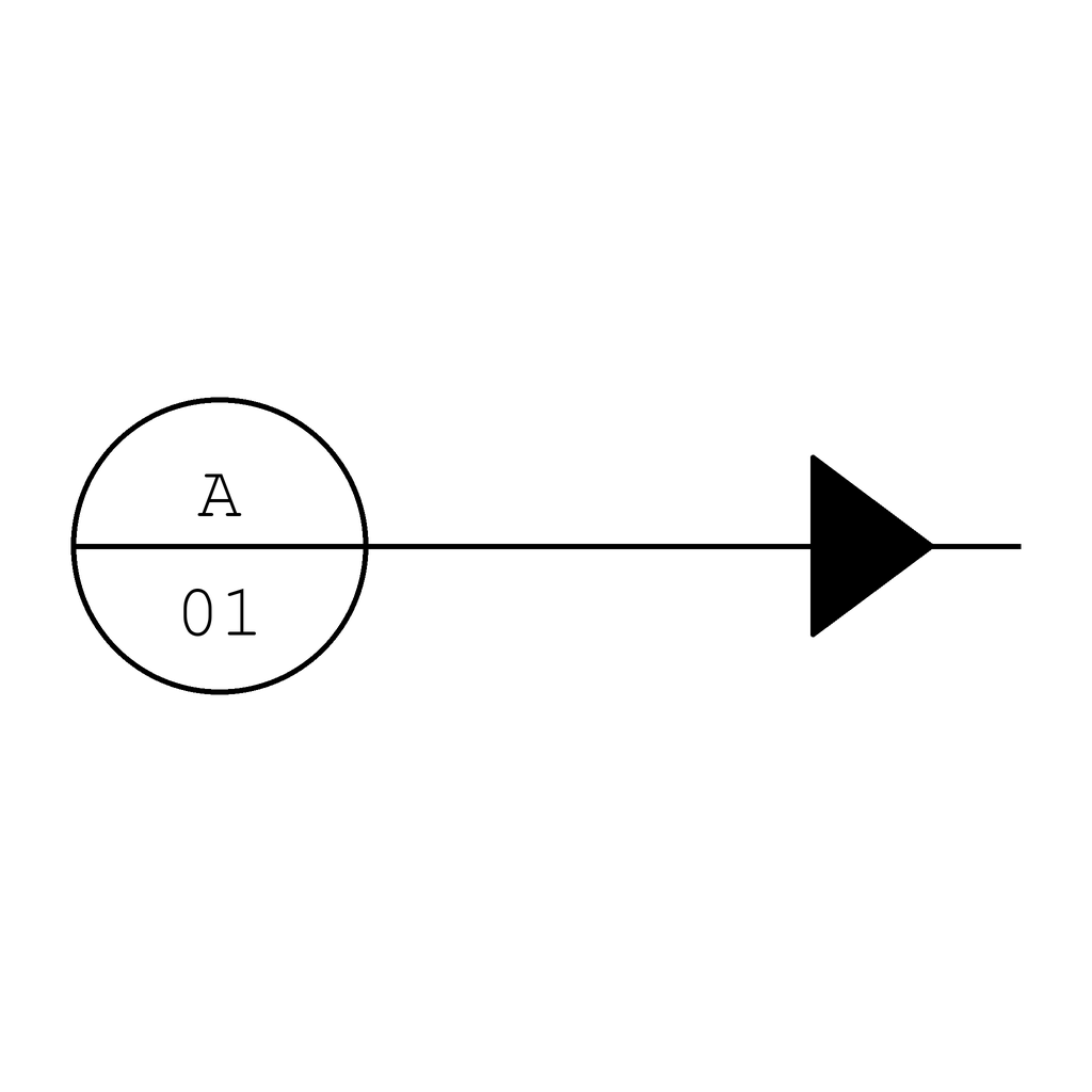
66 / AnnotationElevation markerTypical / 14 × 10 mm paper graphic at 1:1

Paper graphic at 1:1
Typical size: 14 × 10 mm paper graphic at 1:1.
Overall drawn extents: 14 × 10 mm / 0.551 × 0.394 in.

Paper size at 1:1. Scale for model space or place in a sheet view.

Sizes are not code requirements. DXF layer: A-ANNO. Select import units explicitly and use insertion scale 1. SVG includes margin; PNG is fitted to a square transparent canvas.

67 / AnnotationDetail calloutTypical / 10 × 10 mm paper graphic at 1:1

Paper graphic at 1:1
Typical size: 10 × 10 mm paper graphic at 1:1.
Overall drawn extents: 10 × 10 mm / 0.394 × 0.394 in.

Paper size at 1:1. Scale for model space or place in a sheet view.

Sizes are not code requirements. DXF layer: A-ANNO. Select import units explicitly and use insertion scale 1. SVG includes margin; PNG is fitted to a square transparent canvas.

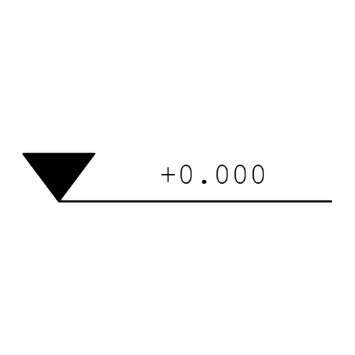
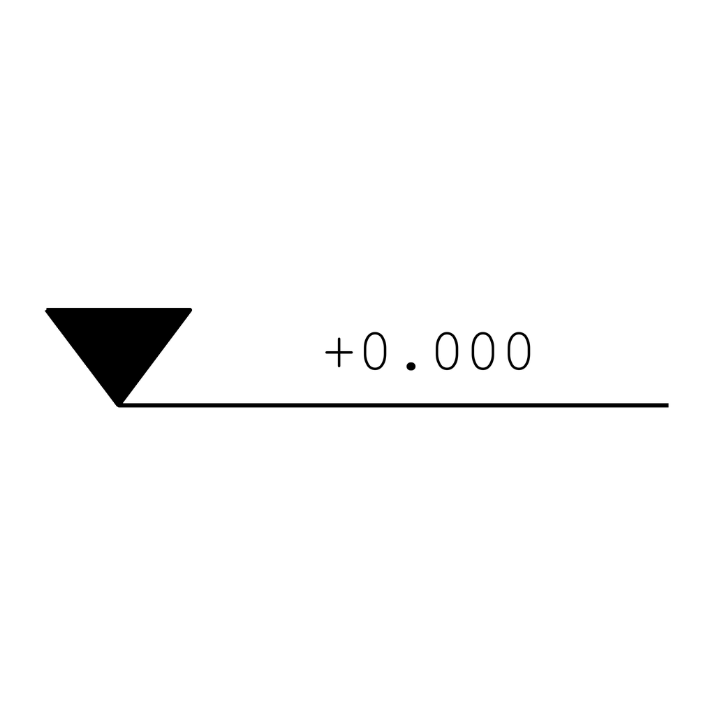
68 / AnnotationLevel datumTypical / 26 × 4 mm paper graphic at 1:1

Paper graphic at 1:1
Typical size: 26 × 4 mm paper graphic at 1:1.
Overall drawn extents: 26 × 4 mm / 1.024 × 0.157 in.

Paper size at 1:1. Scale for model space or place in a sheet view.

Sizes are not code requirements. DXF layer: A-ANNO. Select import units explicitly and use insertion scale 1. SVG includes margin; PNG is fitted to a square transparent canvas.

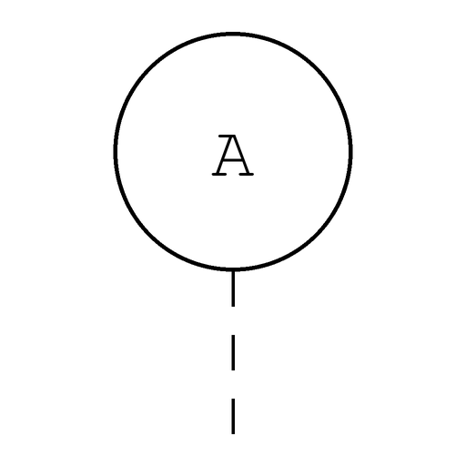
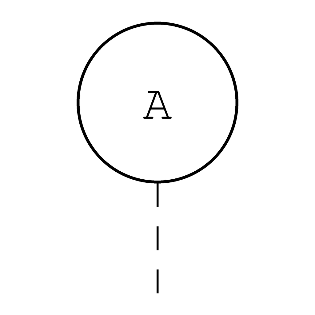
69 / AnnotationGrid bubbleTypical / 10 × 16.8 mm paper graphic at 1:1

Paper graphic at 1:1
Typical size: 10 × 16.8 mm paper graphic at 1:1.
Overall drawn extents: 10 × 16.8 mm / 0.394 × 0.661 in.

Paper size at 1:1. Scale for model space or place in a sheet view.

Sizes are not code requirements. DXF layer: A-ANNO. Select import units explicitly and use insertion scale 1. SVG includes margin; PNG is fitted to a square transparent canvas.

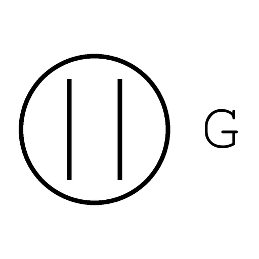
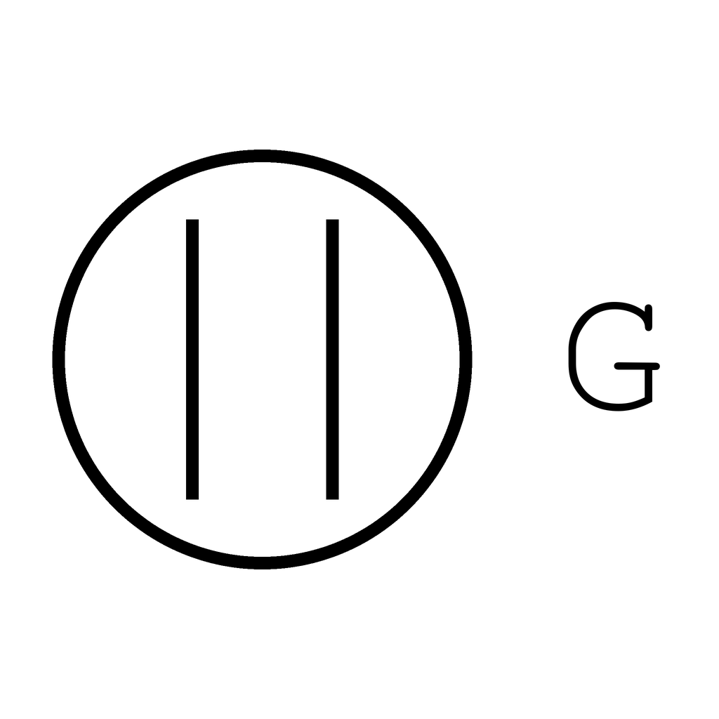
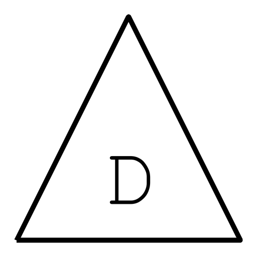
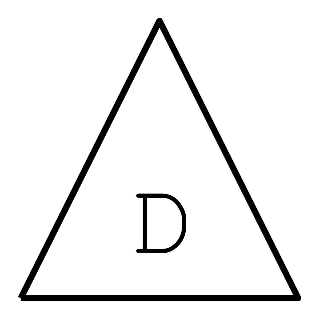
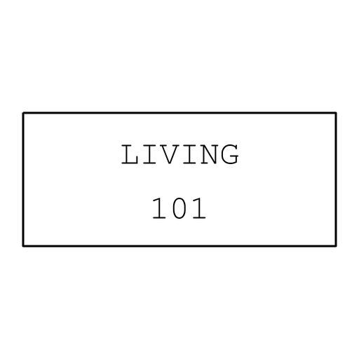
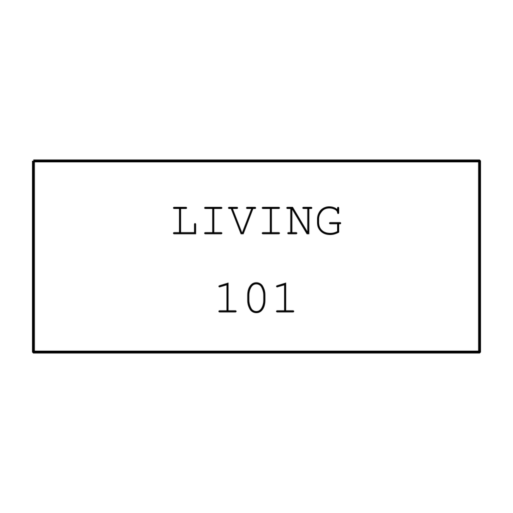
70 / AnnotationRoom tagTypical / 28 × 12 mm paper graphic at 1:1

Paper graphic at 1:1
Typical size: 28 × 12 mm paper graphic at 1:1.
Overall drawn extents: 28 × 12 mm / 1.102 × 0.472 in.

Paper size at 1:1. Scale for model space or place in a sheet view.

Sizes are not code requirements. DXF layer: A-ANNO. Select import units explicitly and use insertion scale 1. SVG includes margin; PNG is fitted to a square transparent canvas.

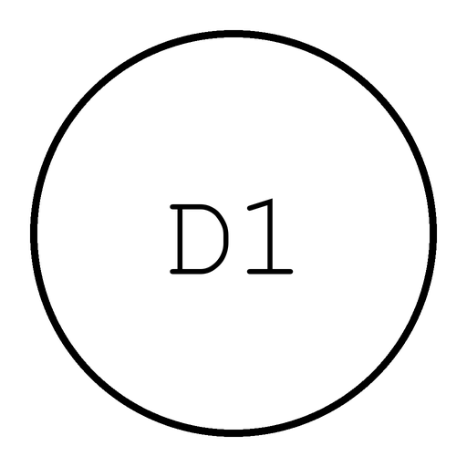
71 / AnnotationDoor tagTypical / 10 × 10 mm paper graphic at 1:1

Paper graphic at 1:1
Typical size: 10 × 10 mm paper graphic at 1:1.
Overall drawn extents: 10 × 10 mm / 0.394 × 0.394 in.

Paper size at 1:1. Scale for model space or place in a sheet view.

Sizes are not code requirements. DXF layer: A-ANNO. Select import units explicitly and use insertion scale 1. SVG includes margin; PNG is fitted to a square transparent canvas.

72 / AnnotationWindow tagTypical / 12 × 8 mm paper graphic at 1:1

Paper graphic at 1:1
Typical size: 12 × 8 mm paper graphic at 1:1.
Overall drawn extents: 12 × 8 mm / 0.472 × 0.315 in.

Paper size at 1:1. Scale for model space or place in a sheet view.

Sizes are not code requirements. DXF layer: A-ANNO. Select import units explicitly and use insertion scale 1. SVG includes margin; PNG is fitted to a square transparent canvas.

73 / AnnotationRevision tagTypical / 12 × 10 mm paper graphic at 1:1

Paper graphic at 1:1
Typical size: 12 × 10 mm paper graphic at 1:1.
Overall drawn extents: 12 × 10 mm / 0.472 × 0.394 in.

Paper size at 1:1. Scale for model space or place in a sheet view.

Sizes are not code requirements. DXF layer: A-ANNO. Select import units explicitly and use insertion scale 1. SVG includes margin; PNG is fitted to a square transparent canvas.

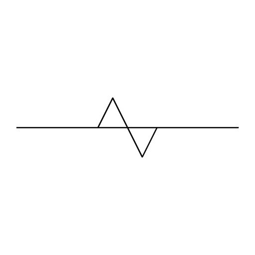
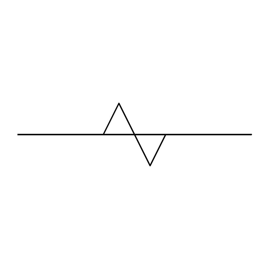
74 / AnnotationBreak lineTypical / 30 × 8 mm paper graphic at 1:1

Paper graphic at 1:1
Typical size: 30 × 8 mm paper graphic at 1:1.
Overall drawn extents: 30 × 8 mm / 1.181 × 0.315 in.

Paper size at 1:1. Scale for model space or place in a sheet view.

Sizes are not code requirements. DXF layer: A-ANNO. Select import units explicitly and use insertion scale 1. SVG includes margin; PNG is fitted to a square transparent canvas.

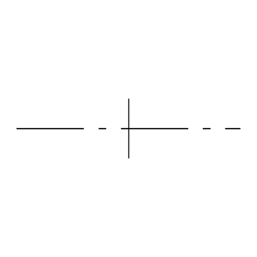
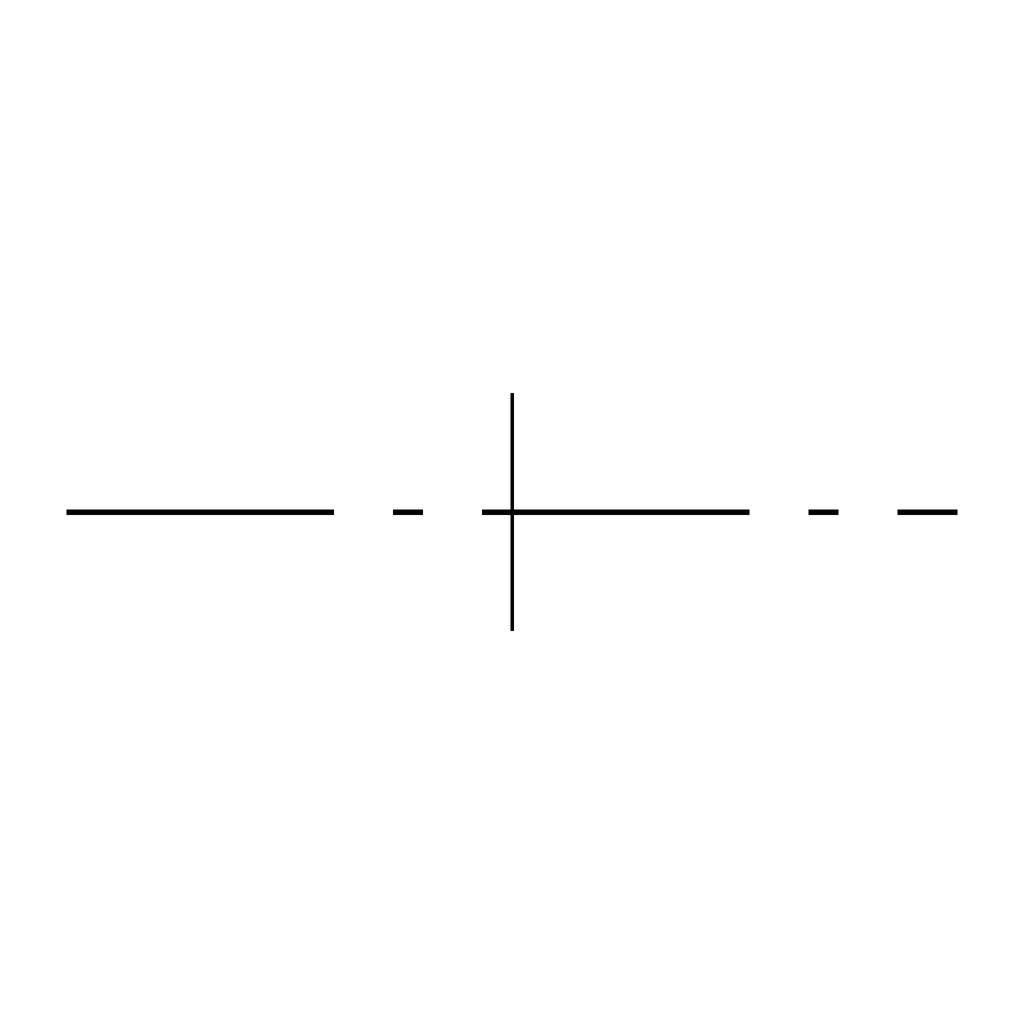
75 / AnnotationCentrelineTypical / 30 × 8 mm paper graphic at 1:1

Paper graphic at 1:1
Typical size: 30 × 8 mm paper graphic at 1:1.
Overall drawn extents: 30 × 8 mm / 1.181 × 0.315 in.

Paper size at 1:1. Scale for model space or place in a sheet view.

Sizes are not code requirements. DXF layer: A-ANNO. Select import units explicitly and use insertion scale 1. SVG includes margin; PNG is fitted to a square transparent canvas.

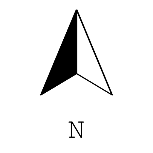
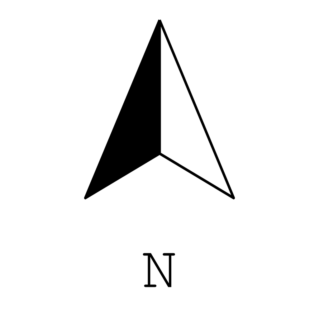
76 / AnnotationNorth arrowTypical / 10 × 18.8 mm paper graphic at 1:1

Paper graphic at 1:1
Typical size: 10 × 18.8 mm paper graphic at 1:1.
Overall drawn extents: 10 × 18.8 mm / 0.394 × 0.740 in.

Paper size at 1:1. Scale for model space or place in a sheet view.

Sizes are not code requirements. DXF layer: A-ANNO. Select import units explicitly and use insertion scale 1. SVG includes margin; PNG is fitted to a square transparent canvas.

Customize a north arrow.

Free for personal and commercial drawings. No redistribution as a symbol pack. Read the licence and unit notes. Both PDF legends contain every symbol and its name. Print landscape at actual size; the fitted reference illustrations are not to scale.

Read the plan before its symbols

Start with the walls, then follow the openings between rooms. A heavier outline helps you find the enclosure; a thinner partition divides the space inside it. A gap in the wall can indicate an opening, while short returns at its edges can describe a casing. Read those marks alongside dimensions and notes. The dashed wall symbol in this library identifies demolition only when you define that meaning in your legend.

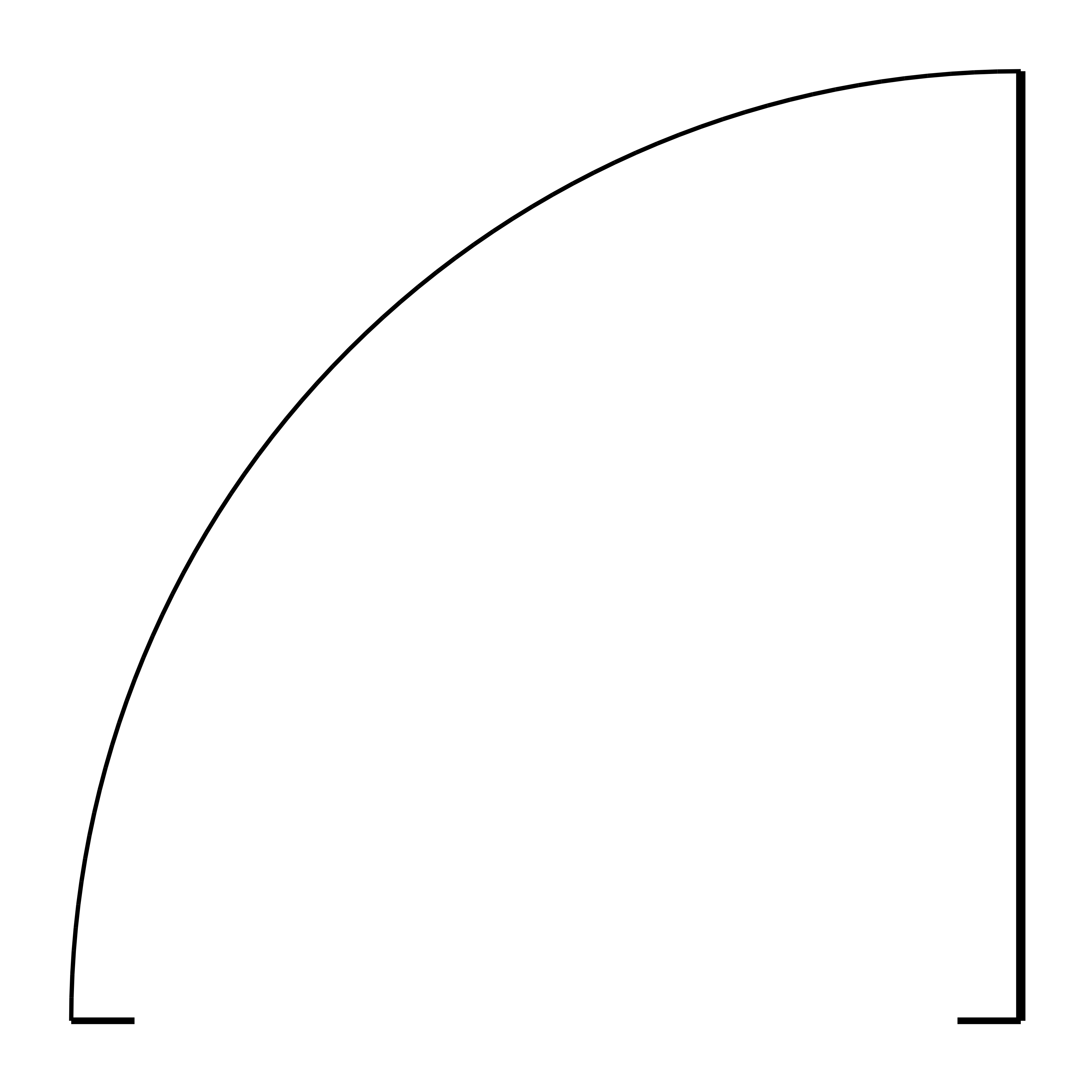
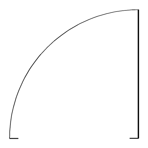
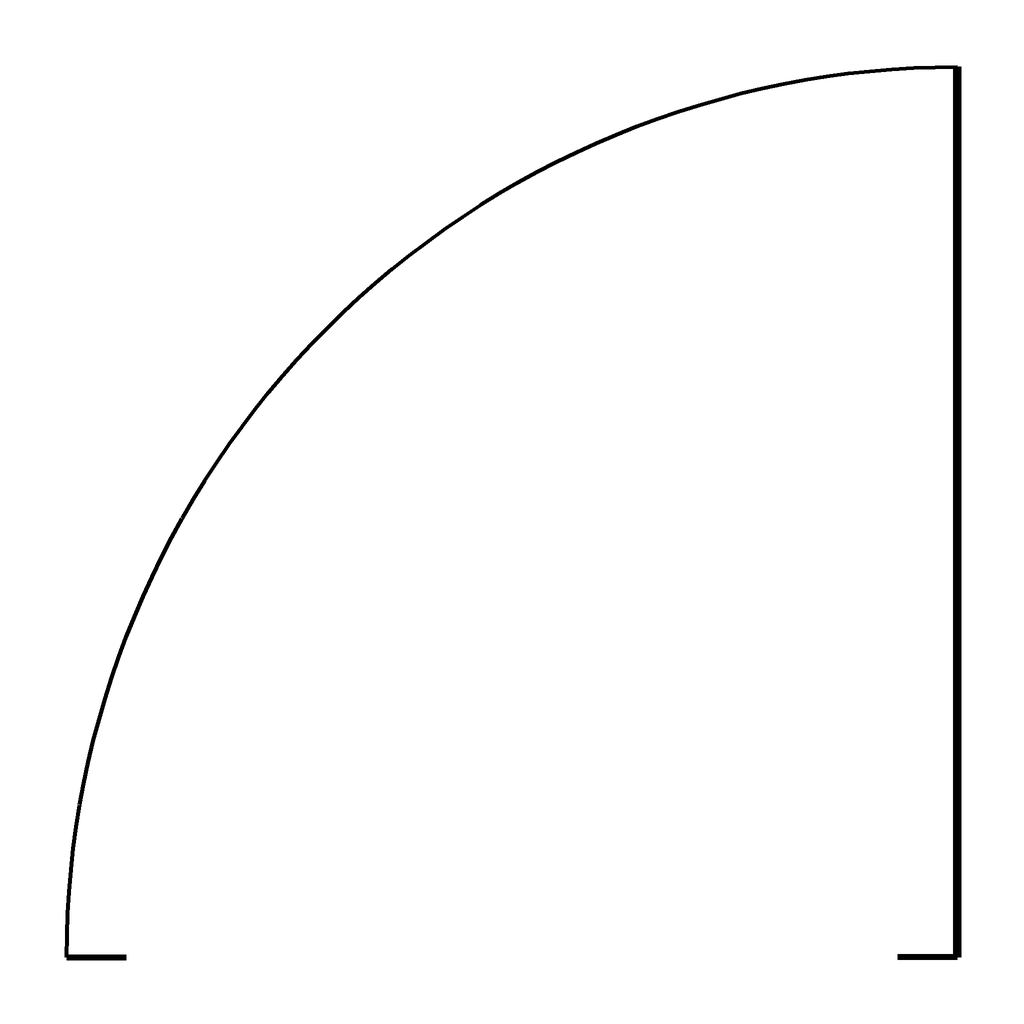
Floor plan door symbols describe the leaf and its movement. The straight line represents the leaf, and the arc traces its free edge as it swings around the hinge. Check the hinge side before placing it. A pair of leaves can meet in the middle; a sliding or pocket door moves along a track. Window lines describe the frame, glazing and sill. Check the window tag against your schedule for information the plan cannot carry.

Follow stairs and changes in level

Read the stair arrow together with its UP or DN label. The arrow points in the direction named by that label, so an upward route can turn across a landing. The break line interrupts the representation where the stair continues beyond the portion being described. It is a drawing convention, not a missing tread. Check the floor level and the adjoining plan before deciding where a stair begins or ends.

Use the ramp arrow to describe the direction of ascent, then add the project's slope and level information beside it. A step down needs a clear relationship to the surrounding floor. These drawings give you a starting graphic; you still need to resolve the stair geometry, ramp slope and changes in level for your design.

Keep model size and paper size separate

The fixtures, furniture, doors, windows and stairs use typical nominal dimensions in model space. Those sizes are starting points, not code requirements. Check the selected symbol's size and footprint before placing it. A bed outline represents its mattress; you need additional room for its frame and circulation. A dining table symbol includes the drawn chairs. A door's overall geometry includes its swing or track envelope.

Annotation and electrical graphics use paper dimensions instead. A callout bubble can remain legible at a chosen print size while the model behind it changes scale. Place these graphics in a sheet view at their listed paper size, or enlarge them by your view's scale denominator when working in model space. Keep physical objects at true size. The detail panel identifies which kind of geometry you are downloading.

Choose line weights and define electrical marks

Keep furniture, fixture details and swing arcs lighter than cut walls. Test a crop at your final printed size so a sink bowl or stair arrow stays readable without overpowering the room boundary. Use hatch patterns to distinguish materials where that information helps. These symbols match Skiaform's drafting style in the templates, with stronger outlines and quieter internal lines.

Electrical and lighting symbols vary between offices and countries, so your plan needs its own legend. Define the outlet, switch, detector and light symbols you actually use. The dashed switch leg here shows a control relationship; it does not describe a cable route. Keep it separate from dimensions and door arcs so the two meanings remain clear.

Insert blocks and prepare presentation plans

Choose the DXF folder that matches your drawing units: millimetres or inches. Select those units explicitly when importing the R12 file, insert at scale 1, and measure a known object before continuing. The combined DXF contains every named block with arranged sample inserts. These are editable drawings; they do not create parametric building components.

Use SVG for scalable line work in a presentation plan. Use a transparent PNG when your layout needs an image, choosing black for light paper or white for a dark background. Set its placed size deliberately because pixels alone do not establish drawing scale. Add a scale bar and a suitable north arrow after checking the final composition.

FAQ

What do the symbols on a floor plan mean?

They describe walls, openings, fixtures, furniture, services and drawing references in plan. Read each mark with the drawing's dimensions, notes and legend to understand its intended meaning.

How is a door shown on a floor plan?

A swinging door uses a leaf line and an arc around its hinge. Sliding, pocket and folding doors use different leaf and track arrangements to describe their movement.

How do you show stairs going up or down?

Use an arrow with an UP or DN label to identify the direction of travel. A break line interrupts the drawn flight; read it with the floor levels and the adjoining plan.

Are these floor plan symbols to scale?

The physical objects use typical nominal dimensions, with sizes listed for each symbol. Annotation and electrical symbols use paper dimensions, so you need to place or scale them for your printed view.

Can I use them in AutoCAD, Revit or SketchUp?

You can use the DXF files where your application and edition support importing this format, with the units set explicitly. They contain editable 2D geometry rather than parametric Revit families or SketchUp components, and native imports have not been tested.

Can I use these architectural symbols in commercial drawings?

Yes, you can use and edit the files for personal and commercial drawings. You cannot redistribute them as a symbol pack.